I have been using the 2.5mm for awhile, along with 18 AWG wire. and trim the crimp tabs down with my side cutters, before i solder the wire to the little header pin inserts
Late last year I ordered, built and programmed some boards, including 5 control boards. All 5 five of them report “PCF8574 is NOT connected/fitted, relay control not possible”. I looked for obvious solder problems, but JLC did them and they look fine. Since we have 6 of the Wemos D1 minis, I programmed a fresh one for each controller board, so there’s no obvious thing to diagnose there either. Any suggestions on further things to investigate would be very much appreciated since we have no working controllers. Thanks!
—edit—
Not sure how I didn’t see the previous comments about the i2c address last time I searched this. I pulled the latest code and went looking to change the address, but it seems like now both addresses are specified. It’s not clear if there’s still a change to be made. So…erased and programmed the board again and it still doesn’t work but the error message is now:
“External I/O interface is NOT connected, relay control not possible!”
Terminal says:
“…
PCF8574 at address 0x20
PCF8574 not fitted
…”
Then it outputs Error State=4 every few seconds.
Have you updated to the latest code?
If not give that a try. The PCF chip has different addresses, and jlc seem to use random ones!
The latest code, searches for the chip on multiple addresses.
Ooh yeah, was just updating my reply with the results. Still weirdness.
—edit—
So as mentioned in the last edit, I did try updating software. It settles on 0x20 and then says “not fitted”.
The chips are super hard to read, but it seems to be a PCF8574T. I looked up the datasheet, but nothing in that helped me understand what address to use.
New boards look great! Can’t wait to get some and starting testing them out.
I notice that using the bom from JLC for the latest v4.40 module the resistors are 1/3W rather than 3/4W discussed above, guessing these been selected because of JLC availability, but will be at the limit when at 4.2V?
Also looks like they are now very low on stock of the 1% too, they have lots of 5% available, assume this could make the issue above worse so best to wait until they restock.
@stuart since you’re redesigning the controller board based on ESP32, would you consider adding some A/D, either the native ESP32 or a separate IC? This would facilitate reading from current shunts for input and output current.
UPDATE: I just ran across your Jan 2021 video, at the end you mentioned a current shunt board with RS485 communication capability. So I assume that facilitates current monitoring. Can I have two, one each for input and output current? Also, will the software someday do state of charge?
Is the controller software capable of driving a latching relay (by sending a pulse to control it)?
Thanks @stuart for all your great work!
Yes to both of those, but the current monitor has not yet been released/finished!
Yes, pulse output is possible - I don’t think its been tested much though
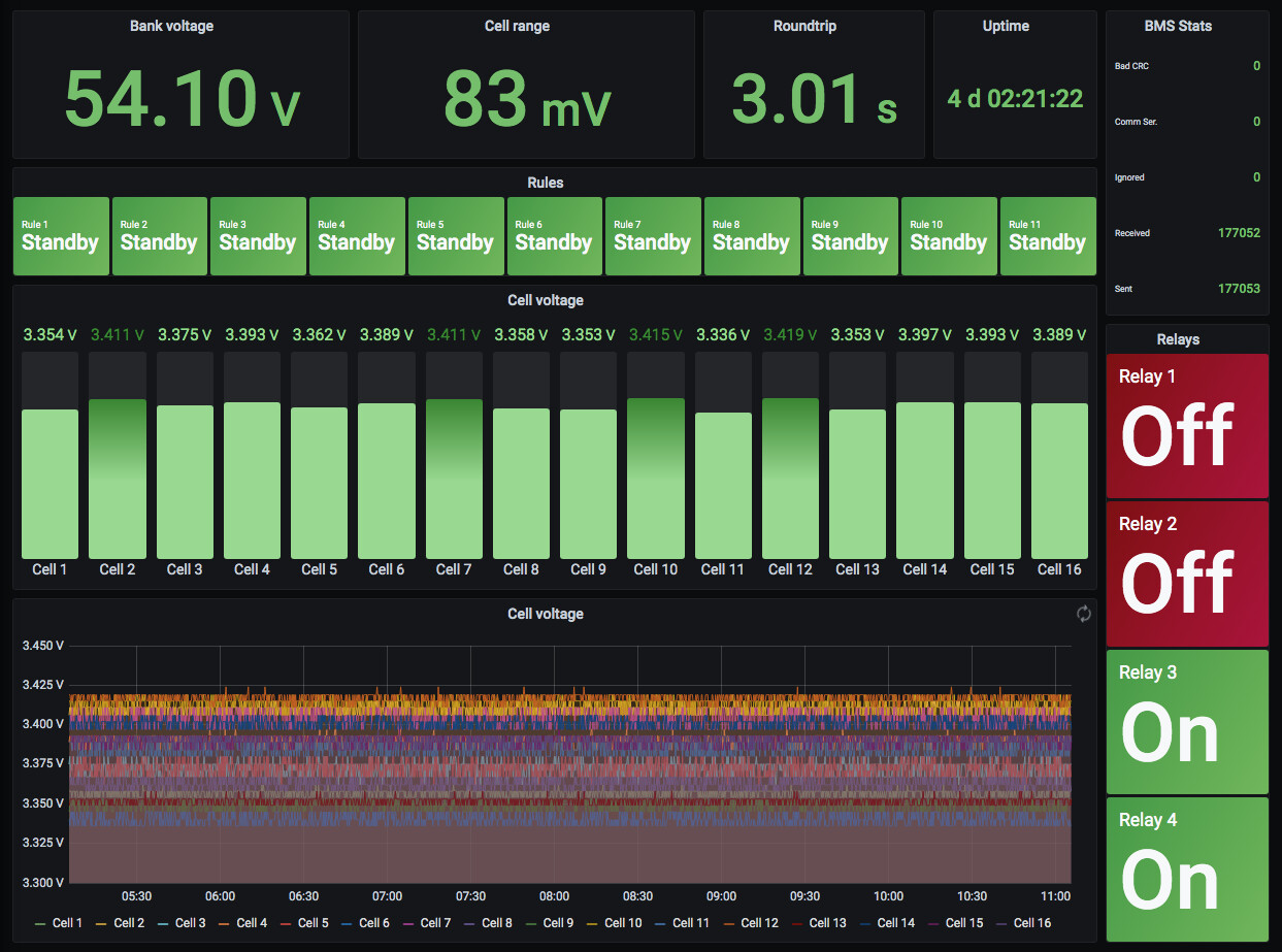
If anybody needs a guide how to do diyBMS → MQTT → NodeRed → Influx 2.0 → Grafana i made one here in the wiki Visualize data from the diyBMS · stuartpittaway/diyBMSv4 Wiki · GitHub
3 Likes
Nice!
The ADC on the ESP32 is very noisy and I would recommend an external IC that takes care of that work, something along the lines of an INA237 (85V max voltage) or INA233 (36V max input) which are both I2C connected.
The ESP32 ADC can be worked with if you take multiple samples and average them, it may also help to add a capacitor on the input pin to smooth out spikes. Keep in mind that it is also limited to only six pins while WiFi is active (32,33,34,35,36,39). The ESP32-S2 or even the yet to be released ESP32-S3 will have more ADC pins available but I have not yet tested the ADC to determine how noisy it is yet.
thank´s
Good spot!
The 1/3W are still in the “safe” zone for use, but near the limit. 1/2W or 3/4W would be better.
I’ll see if they have stock.
Along with the above comment, the current Uniroyal Elec 1210W3F330KT5E specced in the 4.4 module is not in stock and “not recommended for new design”. Not sure if you are aware of JLC Component Catalogue that makes it easier to find what they have.
Great thanks! It would be great if one RS485 board could handle 2 shunts, one for charge and one for discharge. On my boat, I’ll charge at about 110A but typically only draw at 5 to 12 amps, so using different shunts would give me the best possible resolution for each.
Great, missed that one!!
I think I shall have to swap to a larger size, C270971
3.3OHMS ±1% 3/4W
2010 size
and then drop to a 3x3 grid, keeping the same overall resistance, and a total of 6.75W
I’ve generated a new circuit and Gerbers - [https://github.com/stuartpittaway/diyBMSv4/tree/v440-resistorswap]
To be clear (replies above,) this still does not work with the latest software. It picks 0x20 but still says the part is not fitted.
Ok, is this from the debug ouput ?
if you want you can use my Grafana graphic for 14S.

2 Likes