How to get new controller build files? I’m so waiting it to build 72 cell battery at one controller
They have not yet been released, as I’m waiting for the final test boards to arrive.
The existing design copes with up to 100 modules though
1 Like
Hi, what chemistry is that, what voltage are you running at?
18650 Li-ion 198VDC nominal. 55S20P
But currently supported only 64 modules, 4x16. Or im wrong?
2 posts were split to a new topic: Controller shows 60000 ms for the round trip
Hello,
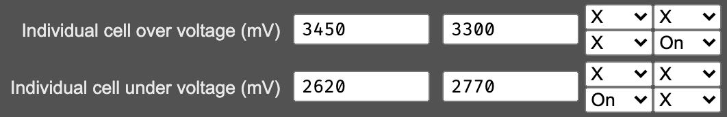
I finally made my system after working on it for a year or so, i need some help to setup the BMS for LiFePo4, anybody using LiFePo4 chemistry which can shed some light on the voltage you have used for bypass and in the rules ?
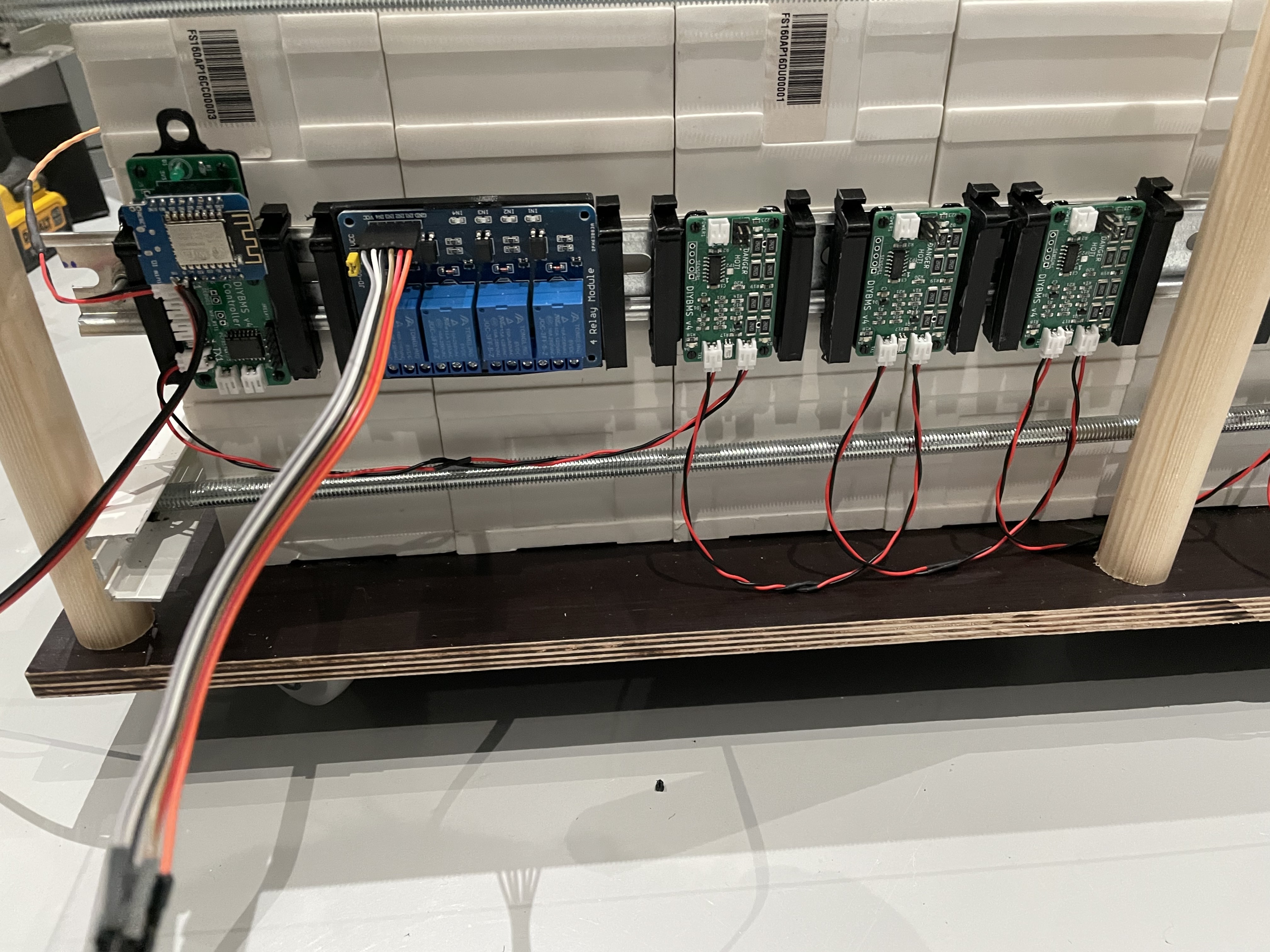
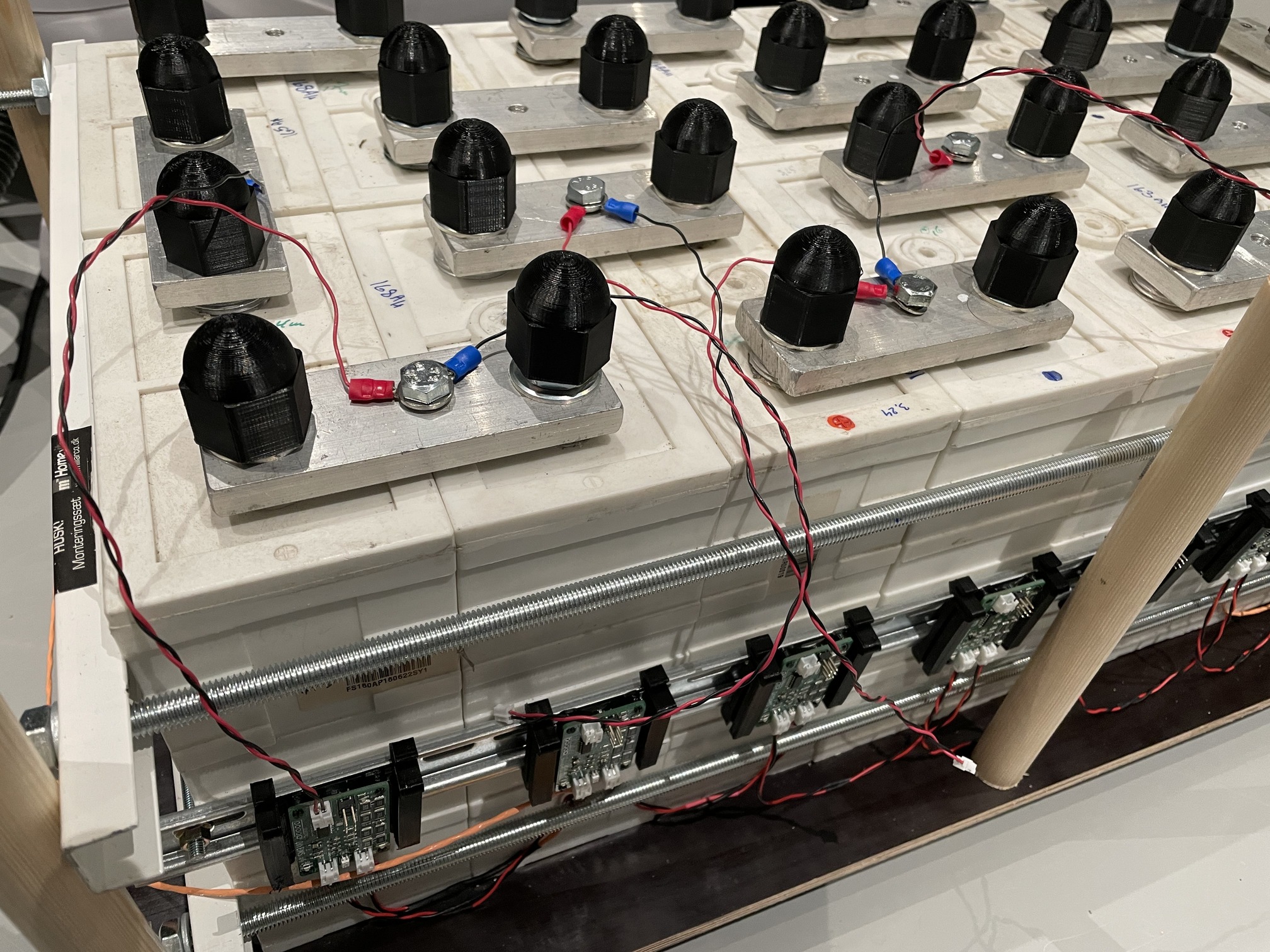
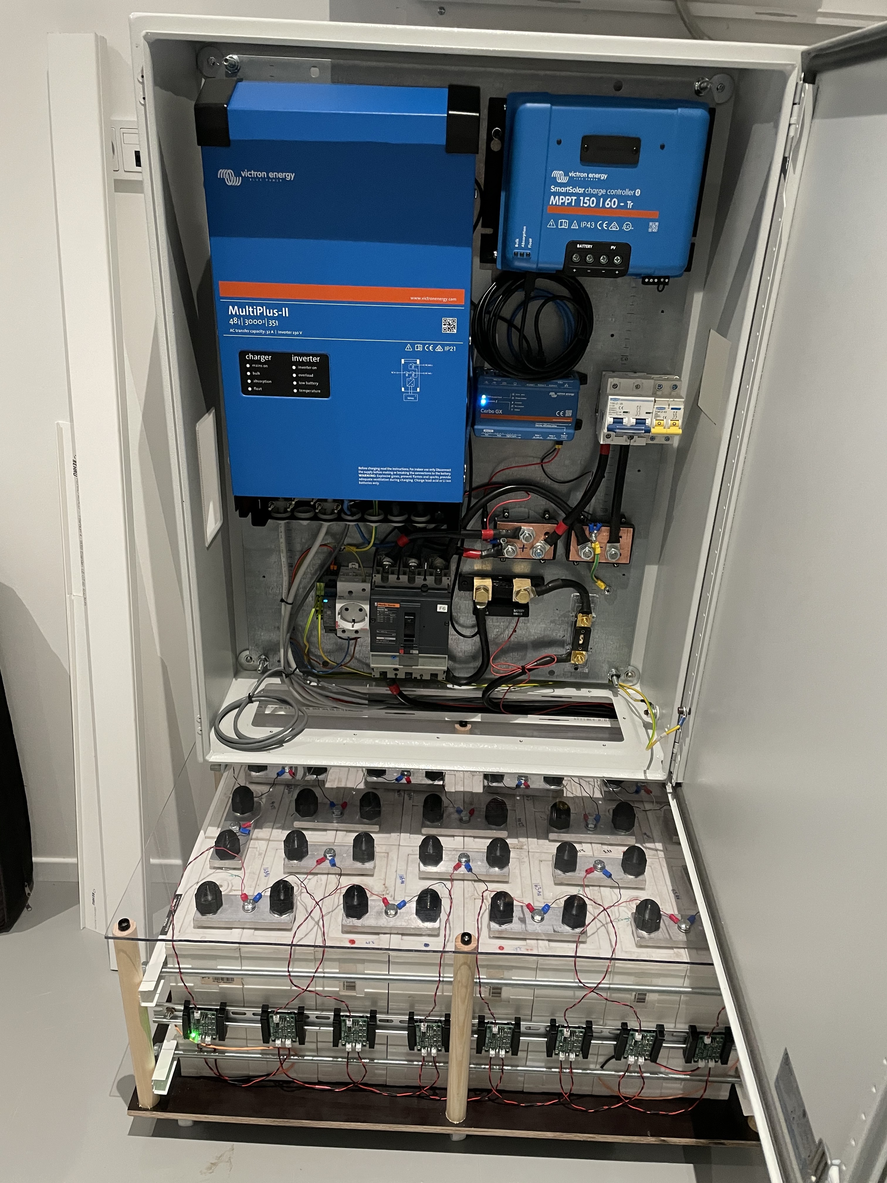
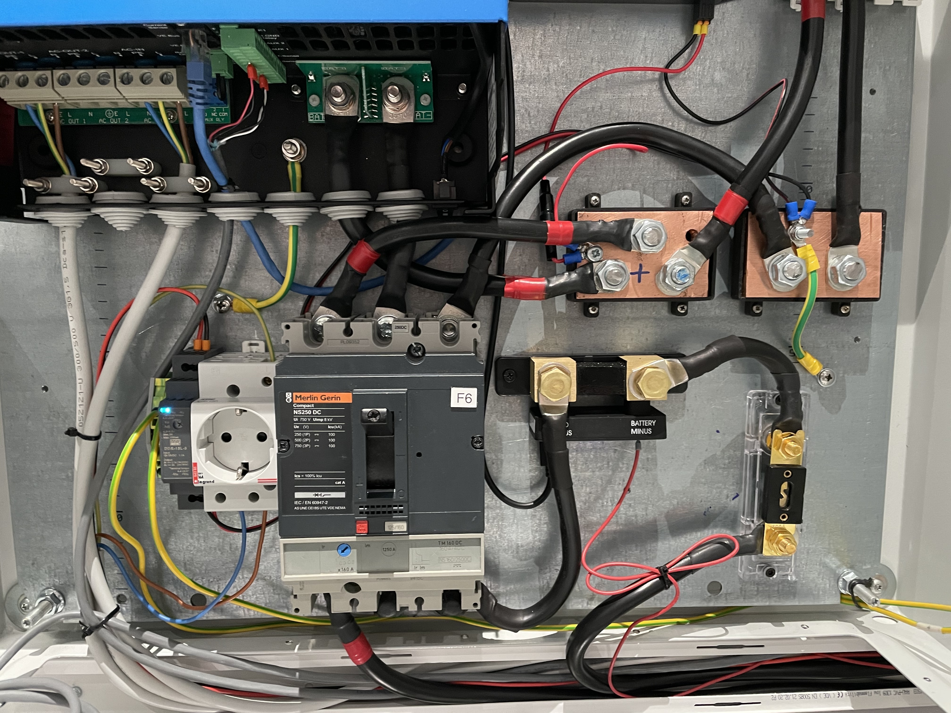
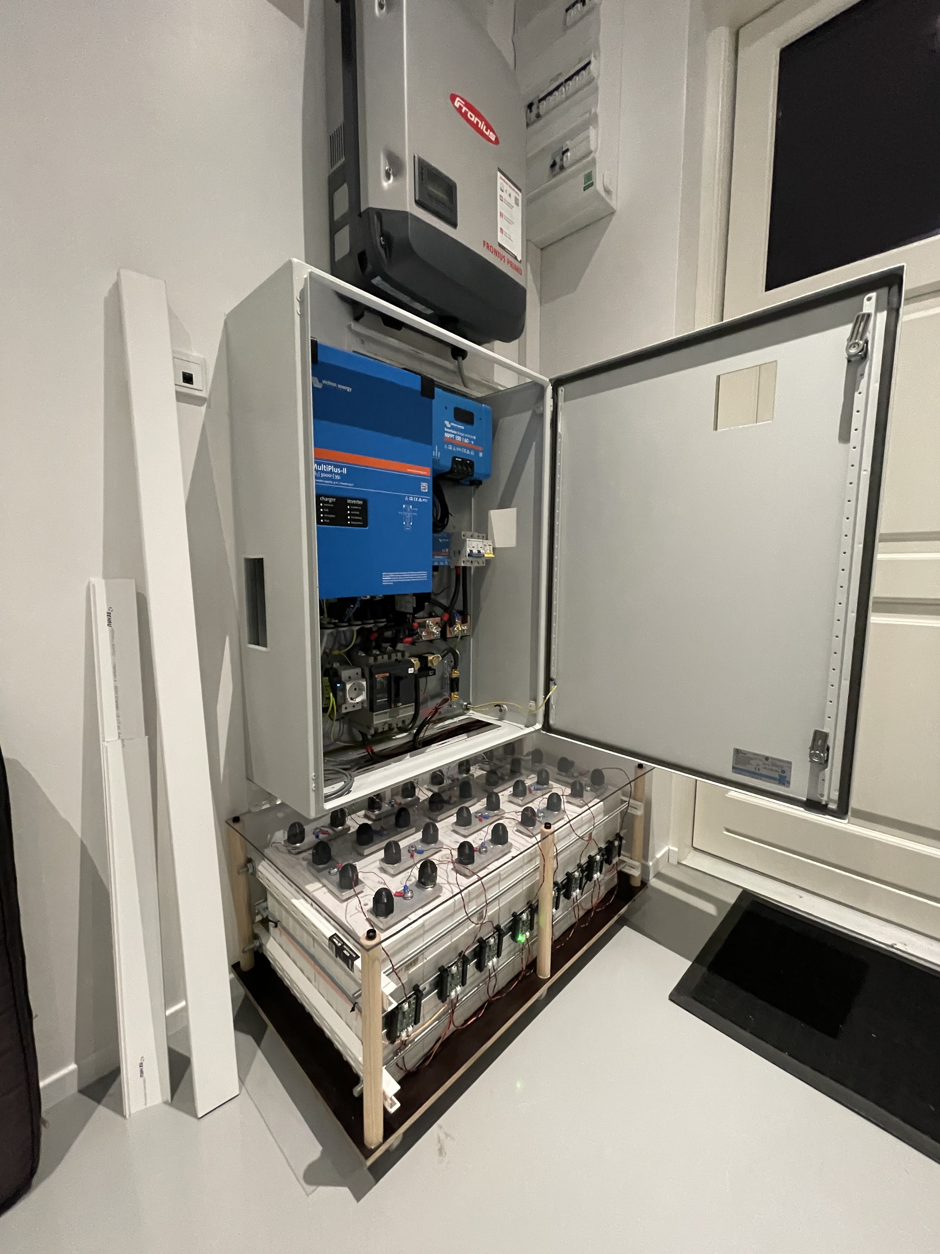
Here are some pictures of my system (consists of 16S LifePo4 160Ah + Victron Inverter + Victron MPPT + Victron Shunt and a Fronius Inverter) :
Work in progress:
Final result :
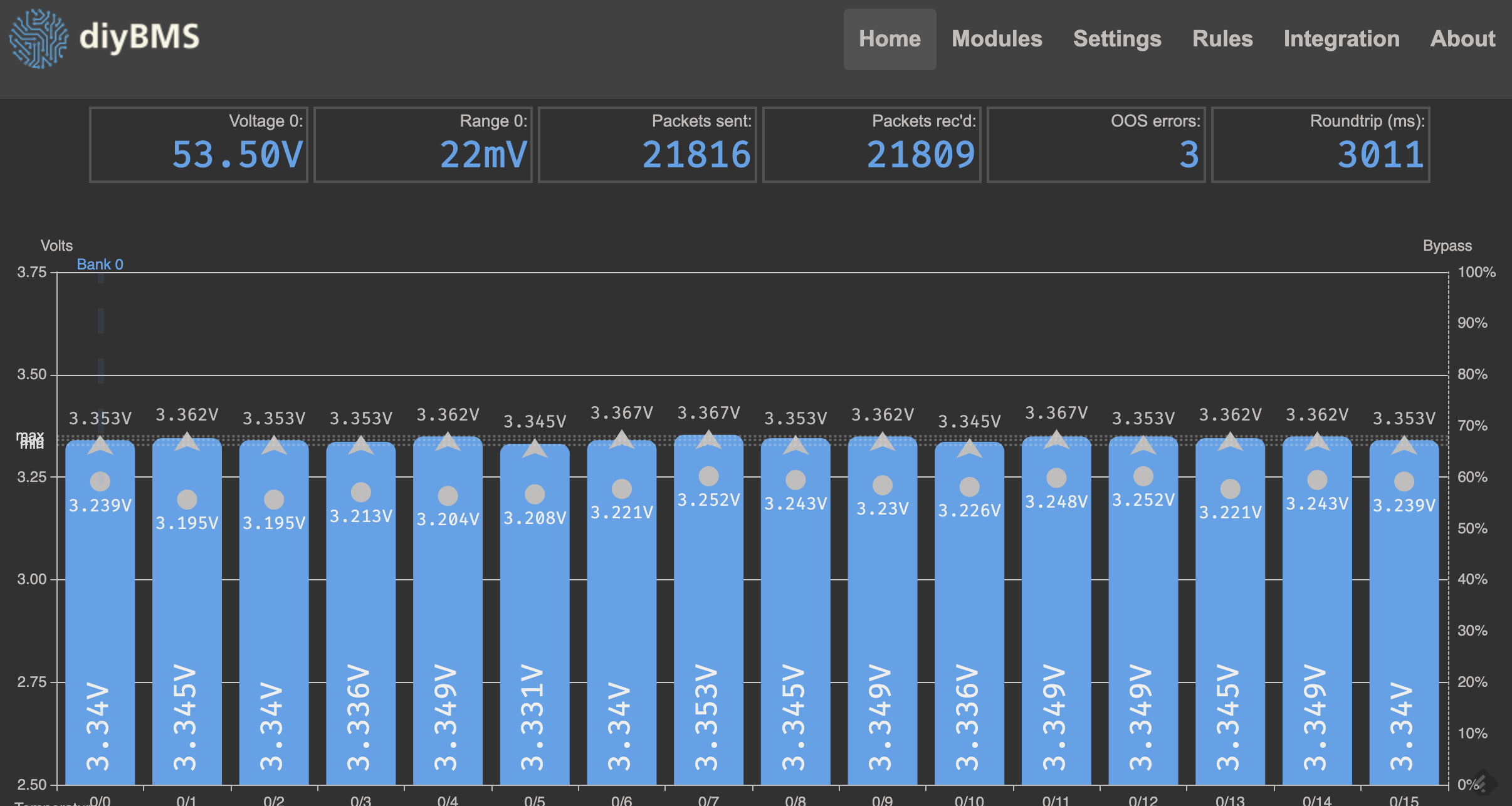
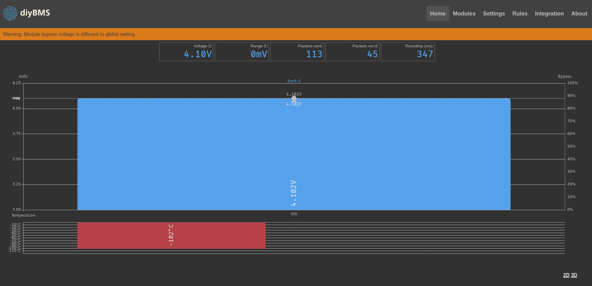
Current view of modules :
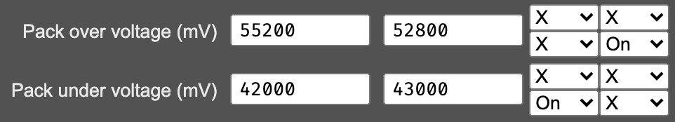
Current settings and these i don’t know if they are correct, this is what i need help with :
![]()
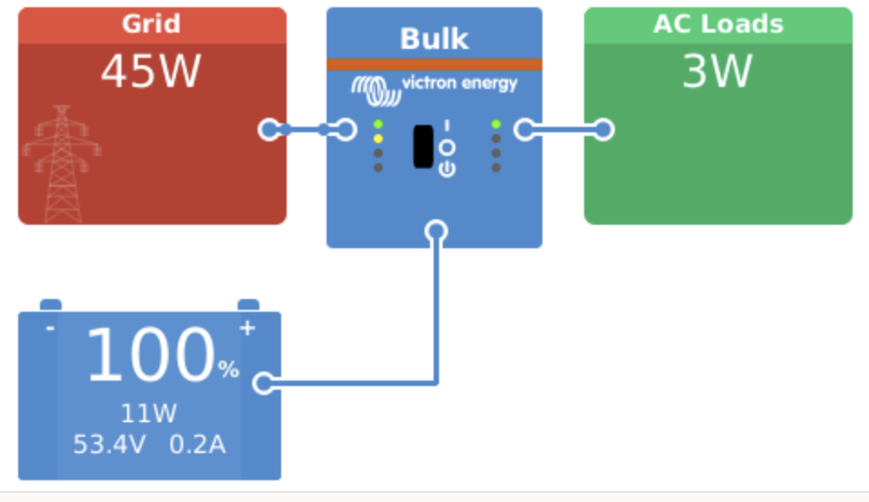
Victron view at the moment 
3 Likes
Up to 32 in series and up to 16 in parallel - total of 100 cells, so you could have 32S x3P or 14S7P etc.
1 Like
sorry to boring you with that, anyone have an idea about this C2 capacitor close to 432 chip in leaf pcb but not on stuart v421? can stay in place or better to remove it?
My leaf board are under production and i have received my big set of attiny 841
I doubt it will do any harm.
as said ive been running 8 months exactly how it was designed works fine
Oups…This design with 432 chip (réf 1.25v)was already like this 8 month ago so sorry I think this is an early mod because there is no available LM4040 (ref 4.1v) on JLPCB
If you running nicely this design for 8 month it is perfect .
Thanks for clarify this
@stuart @Robert.Wall Do i understand correct that if i wire the relay to NC normally closed then without power the relay is closed circuit and when power Off = Closed Circuit and On = Open circuit in the rules page ?
I cannot answer for what happens inside DIYBMS, but for any hardware relay or contactor, the N/C contact is closed in the ‘normal’, that is the un-powered, state. For the N/O contact, it’s open in the un-powered state and closed when the relay is powered.
Stuart must tell you how the state of the relay (powered or un-powered) relates to the logic.
Hello Stuart,
My first post here, will this new DIYBMS v4 support 18050 battery bank with 14S80P?
And LTO bank with 24S2P (max voltage at 64.8v)?
You betcha!
Both old and new controllers will support that configuration. I’ve recently designed some boards for LTO style voltages and they are being tested by a couple of forum members - take a look at DIYBMS for Lithium titanate battery cells (LTO) - #11 by stuart
First, @stuart thanks for your help.
I have already been able to make a module work, I have tried several plates one by one, but when I try to put two or three in series it only shows me one column, the cables I have checked. Each separate module shows the battery, joining them not
1 Like
Ok, have you gone to the settings and selected how many modules you have?
Why is the temperature wrong? Perhaps a soldering issue on the ATTINY chip?
im having same issue i believe …
@stuart
i was able to flash newest firmware. But now if i connect more then one board, it only shows one and on top of screen indicates “Controller found (2/3/4…) modules, but is configured for 1.”
AND in settings if i set how many numbered of series cells, about 20sec later just reverts back to 1
when i set number of series cells the green leds on modules will flash once “in sync” one after the other like they should. they also do the same on initial power up.
so the controllers see’s all the modules but wont save the number of series cells i set in settings…