Hi @AndRe, I’ve finished off the LTO design and circuit.
Apart from the shape the circuit layout is identical to the standard V4.21 with the following changes:
- Sensor header is split into 2, with a JST socket for external temp probe
- Voltage divider resistors values changed for 3.0V max input
- Uses TL432CSF part (LCSC code C126100) to replace the obsolete TL432G
- LED resistors reduced to 1K to ensure they are visible at lower voltages
- Thermistor changed to 10K 3950K NTC - SDNT2012X103J3950HTF (cost reduction)
- Thermistor resistors changed to 10K (cost reduction)
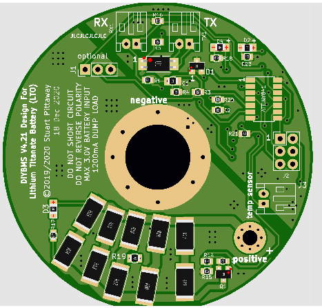
- PCB is 62mm round to bolt onto end of NEGATIVE LTO cell/terminal.
Drop me a message on this board when you are ready to order some from JLC and I’ll send you the files.