Correct but the charger doesn’t know the information about the single cell, that’s the BMS job to alert the charger.
Agreed, although in practise, the cells shouldn’t be that out of alignment for the charger to have to be forced to stopped by the BMS.
I am still having issues where the relay for the shut trip is being randomly triggered, can anyone else confirm if they are having the same issues ? or is it maybe just my relay of controller ?
Hi Rolf are you using the code from the relay branch in GitHub or the master branch?
Is the esp8266 rebooting causing the relay to toggle?
Hey @stuart, I am using the master branch was not aware there was a relay branch, this there difference ?
I if reset the controller from the ui, it will sometime cause the relay to activate and trip the shunt but its randm, but these last few trips the controller has been running for a while and it’s tripped the shunt at least 4-5 times, It used to be much worse but that was when I didn’t have the D1 mini pro and the esp8266 would loose wifi due to my powershed being made of all steel and insulated with foil bubble wrap, so I change to a D1 Mini Pro and added the external antenna, since then I have never not been able to reach the controller. I assumed at the time the controller was resetting/reboot when it lost wifi, but now I’m not that sure it’s the cause, though it has been a whole lot better. My internet is generally ok we have fiber, but is does maybe at times drop, I would say maybe once a week if that.

I will add that, I have a friend who is also running 4P4S and using the same batch controller and modules as we ordered together, only difference is we have different relays, I have a single relay which I’ll switch out and let it run and see if that’s the cause. If the cause is due to the PFC ship going high/low then maybe there is a simple circuit I can add that will delay the current to the relay, for example a cap or resistor ? where is the applied 5v current needs to be for at least 5sec before it reaches the relay board.
Yes, try it out - it implements hysteresis rules so you can now set min/max values for the relays to trigger on.
https://github.com/stuartpittaway/diyBMSv4Code/tree/HysteresisRules
Shot I will give it a go
@stuart i tried hysteresis branch on the controller, should i not expect some more settings in webinterface ?
I just do an upload again in VS Code after i switched branch but i can’t see anything new.
Did you “upload file system image”?
Umm not sure but since I am not sure then I am sure I didn’t, how is that done ? I just clicked “Upload” is there another option from VS code?
Update: found it and it works. thx
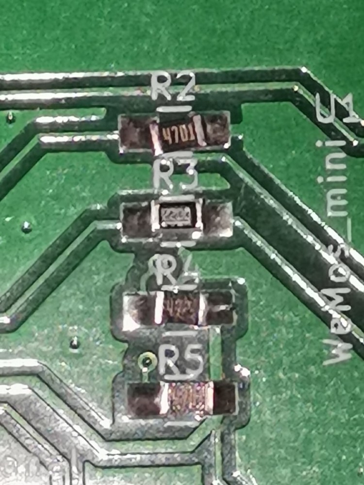
@stuart i ran out of the power resistors Ever Ohms Tech | Ever Ohms Tech CR2512F2R20E04S | Chip Resistor - Surface Mount - LCSC.COM so i need to order new ones but can’t wait for LCSC so i found these CRCW25122R20FKEG Vishay / Dale | Mouser Denmark , i see no reason why they shouldn’t work, same specs, do you see any issues ?
i am making v.4 boards.
The resistor looks okay. For V4 boards the key points are:
- 2.2 ohms
- 1 Watt
- 2512 SMD size
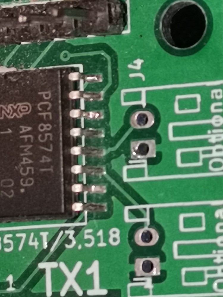
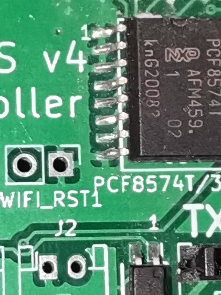
Sometimes an error pops up “PCF8574 is NOT connected/fitted, relay control not possible!” after loading. If you restart several times, the power supply sometimes disappears. What could it be?
I suspect that’s a bit of bad soldering - check the connections around the PCF chip.
@stuart not sure if this question has been asked before, can different version modules be used together for example 4.21 with 4 ? i presume yes since the communication is the same but just to be sure i ask, not that i need it now but you never know if one board goes south and i only have one type of replacement.
Yes all versions can be mixed and matched.
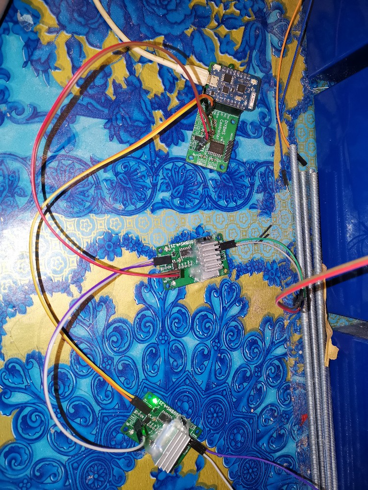
I finally had time to finish my DIYBMS cell units.
I liked them to have heatsink.
With no good way for me to mount them, I used the simple and usually safe for electronics “hot glue”.
I might regret this on later phase, for now the cell PCB are horizontal, and the heatsink is additional aid.
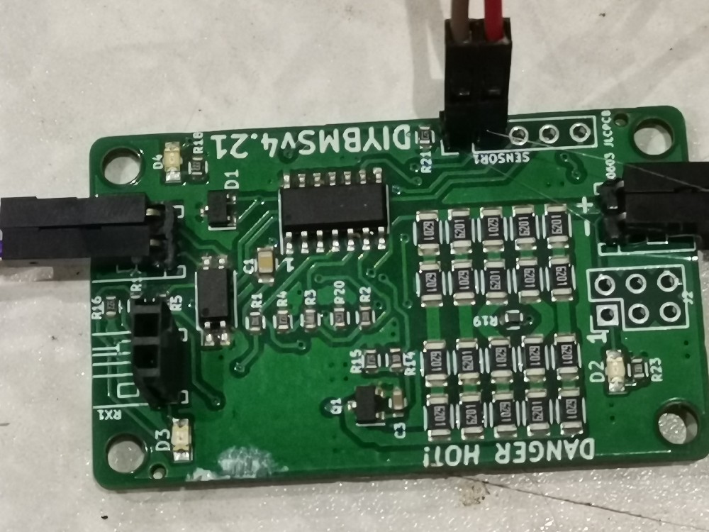
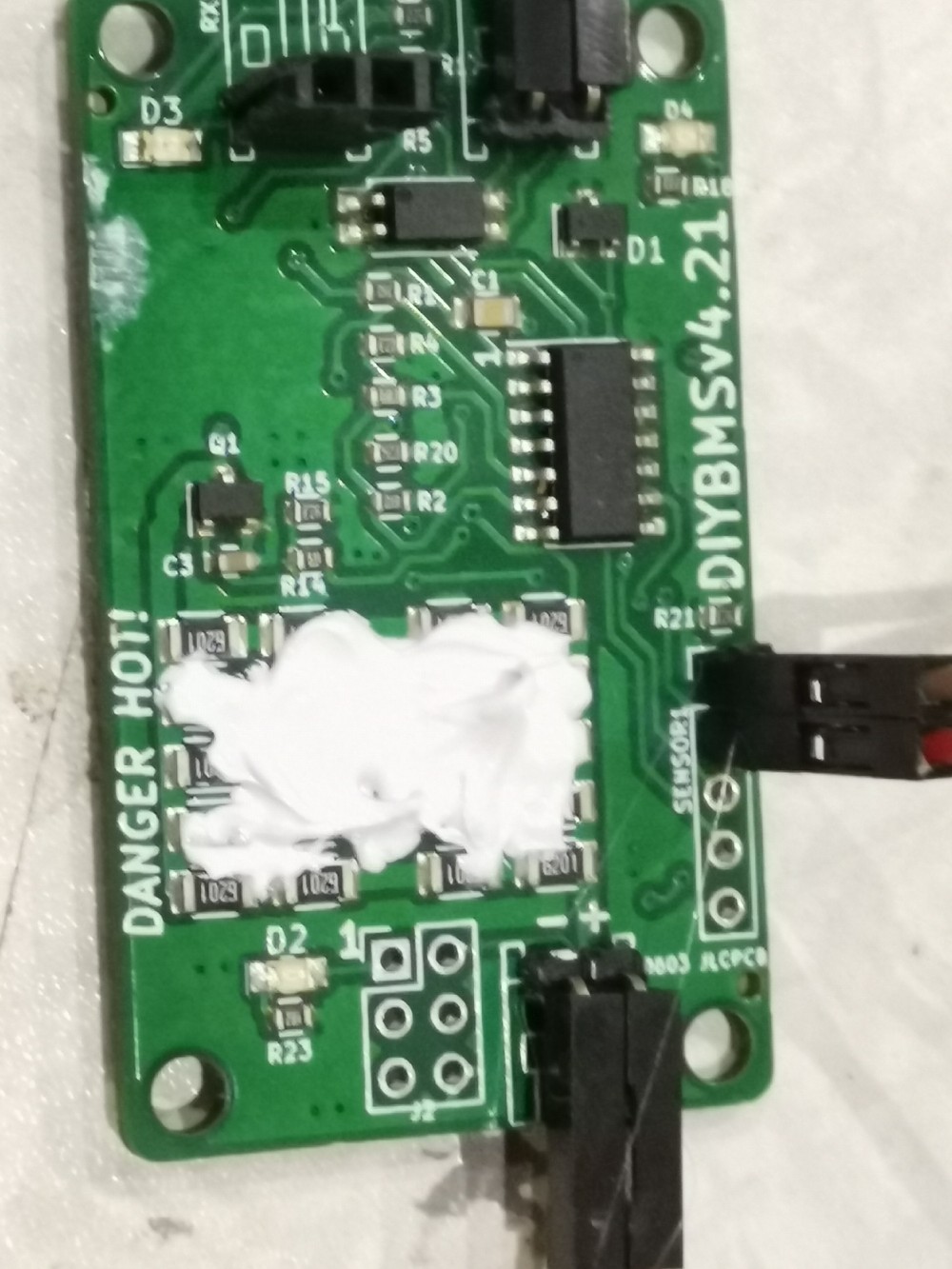
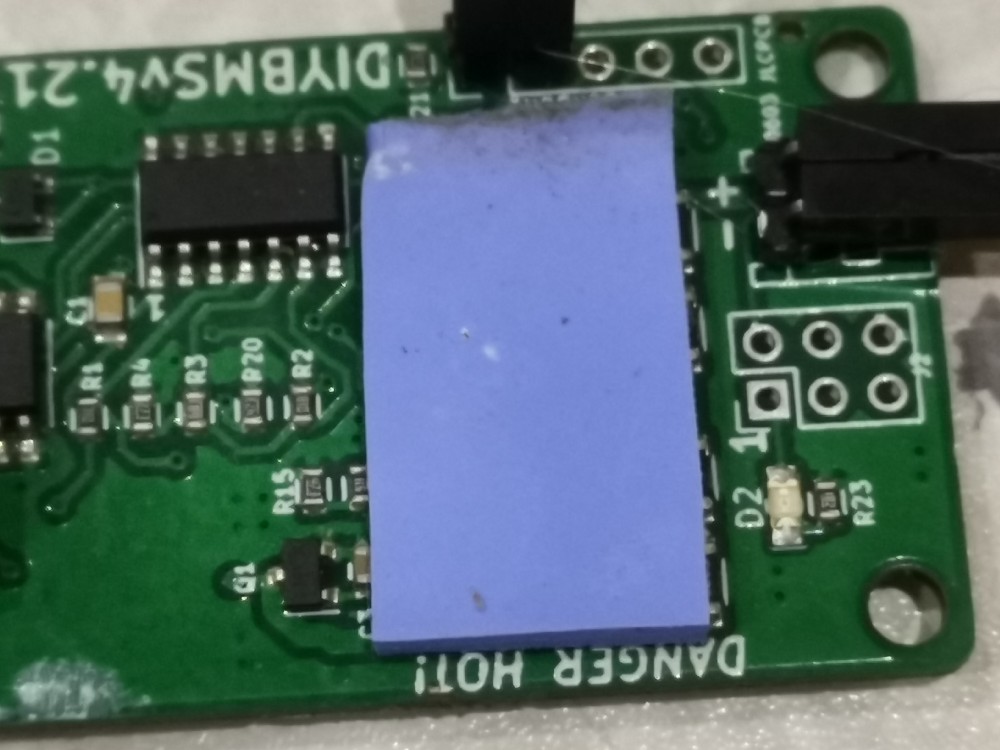
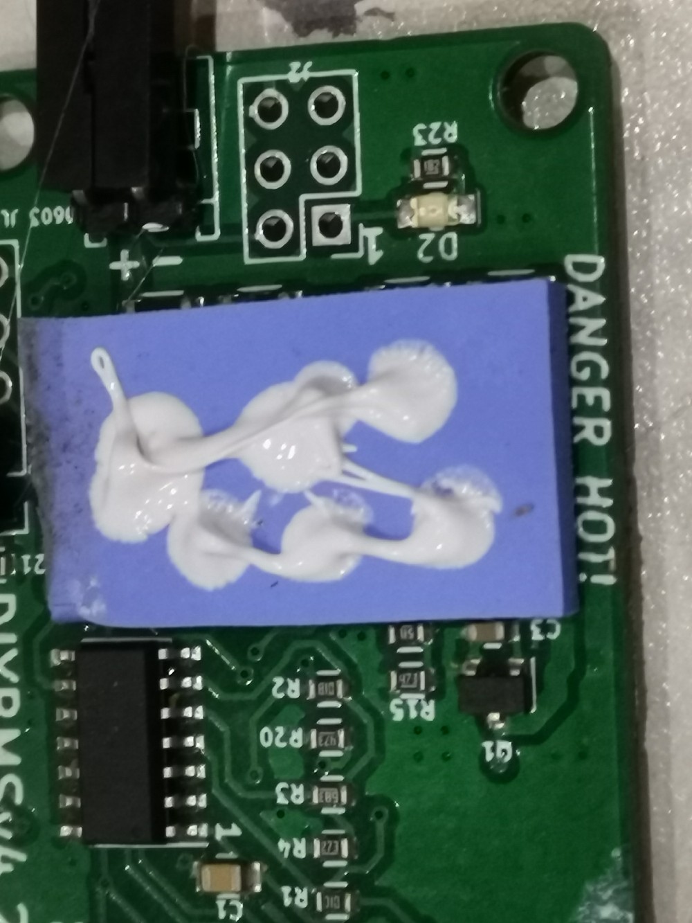
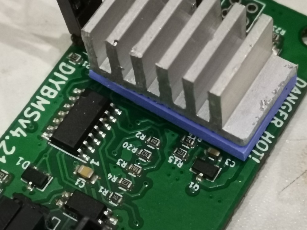
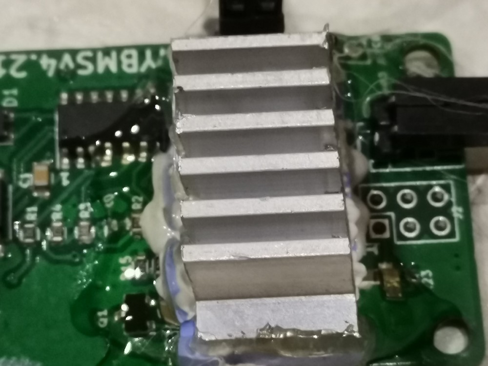
The heatsink doesn’t make contact with any of the other components.
After connecting one controller board and 2 cell modules nothing happens at the web interface.
“The controller is having difficulties communicating with the cell modules.”
The ones not connected to the controller blink twice blue every 5 seconds.
The 2 that are connected blink after 3 seconds, first module 1, then 2, then 1 then 2 and 3 seconds pause.
I made errors during my first order at JLCPCB, and ended up soldering the control module myself.
Not so many parts and it all seems to be soldered OK.
I do not know how I can test!
(Except programming and turn it on 
2 boards soldered, 3 not yet.
It all seems fine, except that it isn’t working.
Can you please point me in the right direction for getting this problem solved?
Thanks!!
@stuart i am testing my diyBMS with a bench power supply instead of a battery so i do following :
- Set the power supply to 3.33V and let it use 1A. (i measure with FLUKE meater that this is indeed the voltage)
- I set the bypass to 3.0V
Now the module goes into bypass and is red. For some time this is working and it pulls around 700mA i can see. The voltage i still keep at 3.33V but the voltage reading in diyBMS fluctuates from 3.33V to 3.23V, is that acceptable ? Seems to much considering the voltage reading i get from FLUKE while the module is in bypass is 3.33V - 3.29V. Also the module blinks red some time really fast, i am not sure if that’s normal and also how long would it try to bybass ? In my simulation the voltage would never go down since it’s a power supply. Is diybms stopping maybe within a timeframe or ?