If there’s an update to the code, is there some way of pushing the updates to all the modules from the controller? I’ve just created 48 modules to monitor my 48 LiFePO4 cells and having to update these individually and manually if and when an update becomes available would be somewhat laborious. BTW, thanks Stu for an amazing project! I’ll be sure to upload photos of my install when it’s all done!
Hello.
The flashing red LED is normal - its the PWM doing its thing to ensure the module doesn’t get too hot. The current should also change over time when the red LED is flashing (it reduces the current to lower heat).
The module is sensitive to the resistance of the wires connecting to the battery/power source - are you measuring the voltage on the module itself?
The module won’t have FLUKE accuracy - but I think that looks good enough for me!
I soldered my third controller board,
Still the same error, with a fresh controler board. it doesn’t see any cell module 
I erased the Wemos D1pro and reinstalled the software.
I do get a warning:
‘SPIFFS’ is deprecated (declared at C:\Users\Frank.platformio\packages\framework-arduinoespressif8266\cores\esp8266/FS.h:269): SPIFFS has been deprecated. Please consider moving to LittleFS or other filesystems. [-Wdeprecated-declarations]
and an error:
cannot open source file “stddef.h” (dependency of “ESPAsyncWebServer.h”)
No idea if they are important, or how to fix…
I’ve added now 3 modules…
all seems to go nicely, green lights “walking” from first to second to third cell, twice, then 3 seconds pause and it walks again.
removing one the the connection cables does provide expected behaviour, blue flashing.
reconnect, its green again. (by standard I disconnect the power for the Wemos when playing with RX and TX cables)
Any ideas on how to troubleshoot this??
The SPIFF warning can be ignored - You shouldn’t get the stddef.h error though. Perhaps try a “CLEAN” on the VSCODE before build/upload. If the controller is working and you can see the webpage - no need to reflash it won’t fix anything.
Simple hardware debug procedure…
- With no modules connected to the controller, you should get the web page and lots of errors.
- Build a temporary loop cable to connect the tx and rx together on the controller - you should get lots of “ignored” errors. This proves the controller is working and wired up.
- Connect a module one at a time - they should just appear on the web interface one by one.
If any of the modules don’t show up, you have a soldering and/or programming issue with the module. When you upload don’t forget to use the “burn fuses” option on the ATTINY.
I just got mine up and running and realised that the wires from TX/RX between the controller and all modules need to be crossed over ie. not straight. My pre-crimped cables are all straight through so I’ll need to redo all 50 of them
not crossed over will prevent the signals from the modules to reach the controller ??
I havent twisted them yet,
I use Dupont wires as they are more convenient for me.
twisting them is easy …
I’ll try and let you know if this helps.
Sadly… no fix.
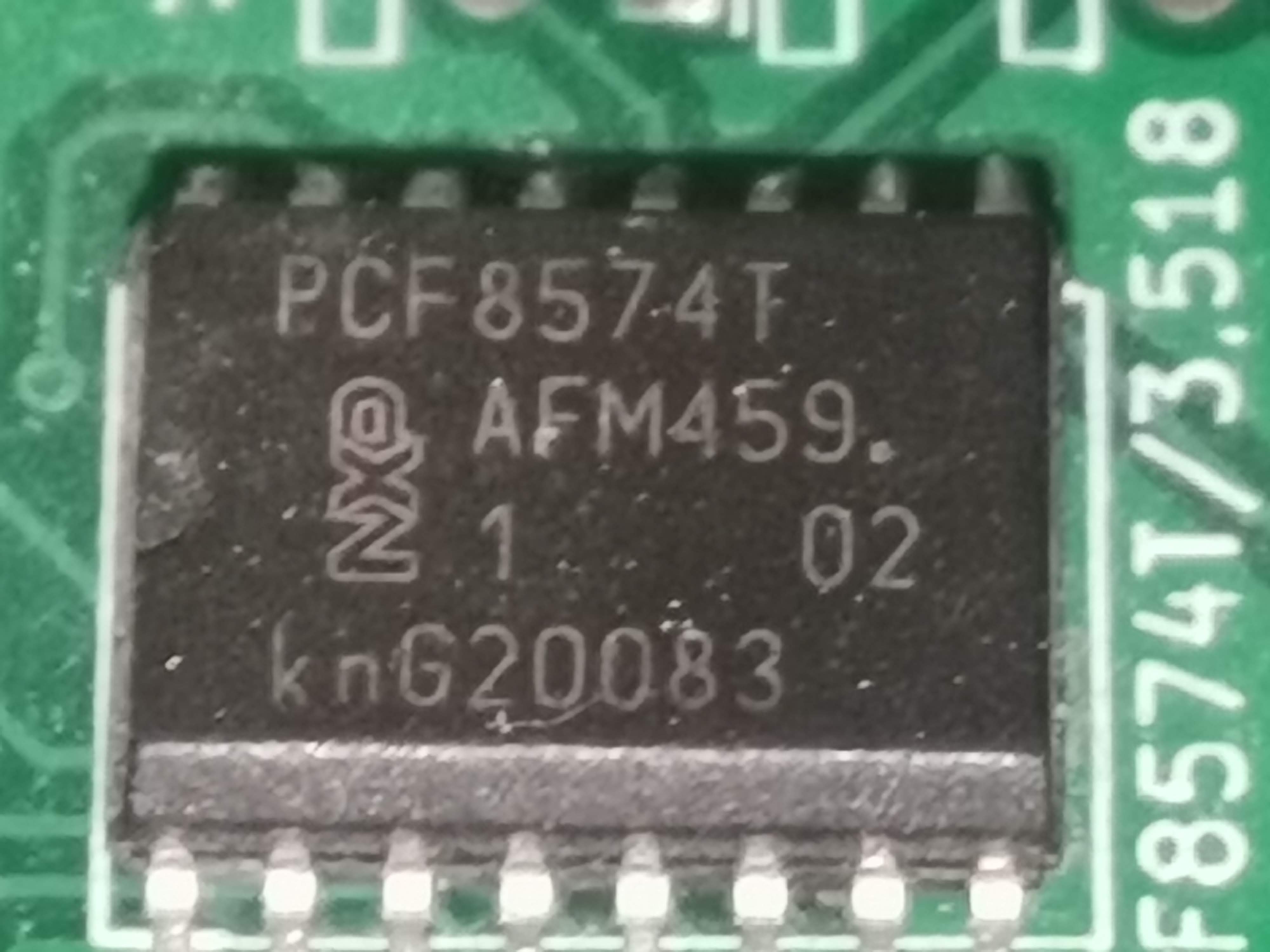
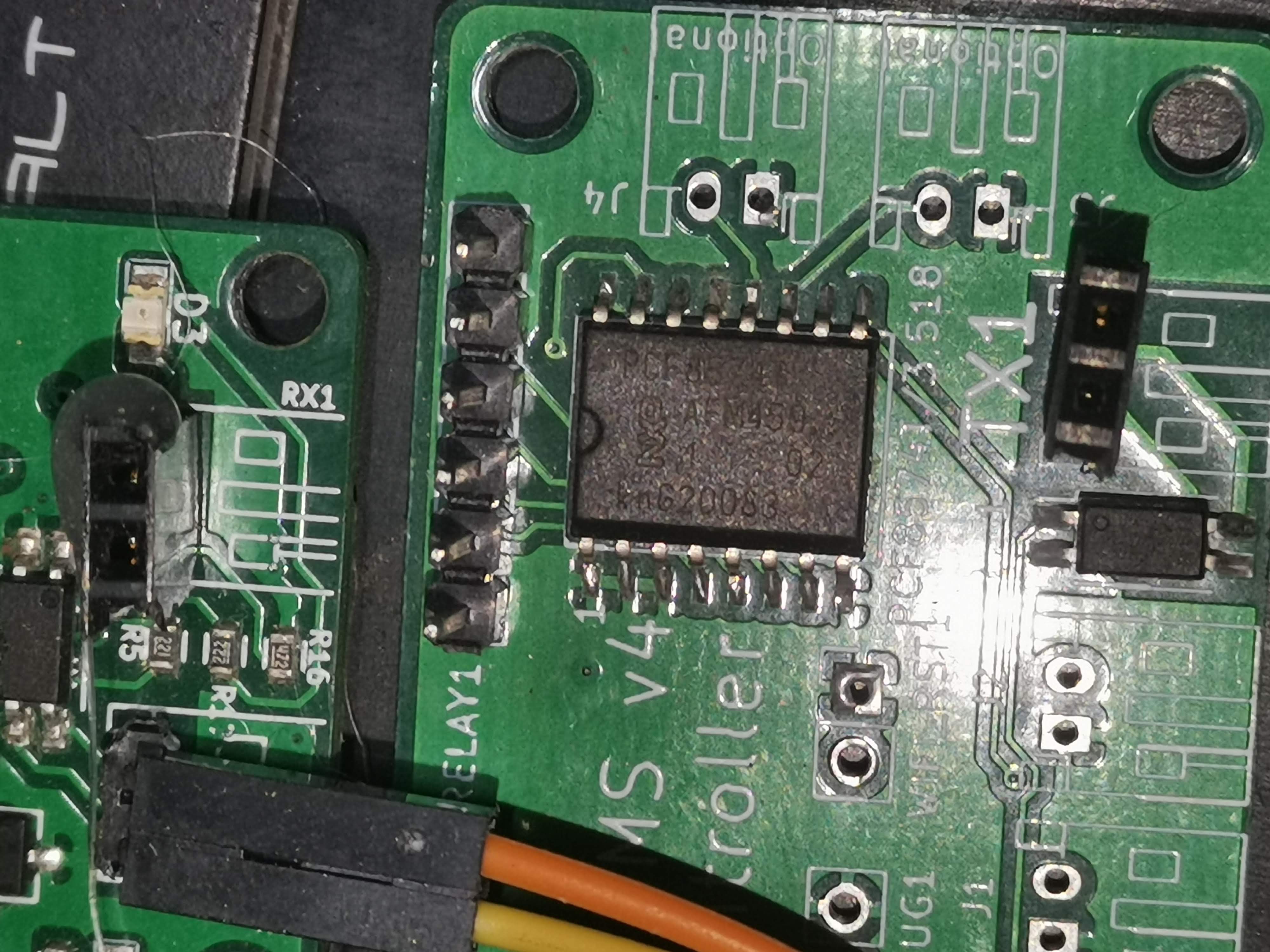
i checked my order from digi-key again for the PFC8574T, it is 3.518 , NXP and I paid 1.44 usd for them (part 568-1077-1-ND)
I’m a bit confused as the PCB tells: PCF8574T but GitHub PCF8574AT/3
there are differences,i just don’t know if they are any important.
other Idea’s??
I’m not talking about twisting, although that will help with interference. I found that if my wires weren’t crossed on the pins that the modules wouldn’t talk to one another. eg:
T -------\  /-------- R
X -------/ \-------- XThe PCF chip is only used for the relay control, not communication with the modules.
There are two different chips - but both work exactly the same, they just have different i2c addresses.
On the JST plugs for the modules - pin 1 on the TX goes to pin 1 on the RX (on next module). This should be straight through.
The controller JST connections should also be straight through - at least according the circuit diagram.
On my test unit it does look like the controller RX/TX pins are swapped from the controller to the first and last modules - never noticed this before!
I’m wondering if the GERBER file everyone uses has this issue, as the circuit diagram is correct!
TX1 to RX1, TX2 to RX2 that was not so difficult to understand 
I’m getting confused now for the twists.
TX1 from the controller goes to RX1 for the first module, yes?
my paint skills aren’t that good…
with the wires straight, the green light blinks.
if I twist them, put TX1 on RX2, all stays dark.
Put TX2 on RX1 the blue (no connection) light keeps blinking its normal pastern
Tx1 on Rx2 and Tx2 on Rx1 lets it all dark (no green or blue led)
RX on RX and Tx lon TX doesn’t work either.
@stuart, can you send me a picture or drawing if the correct setting?
I now use just one cell module as I’m afraid to damage it with reversing TX and RX wires.
I have changed this module a few times, and tried with different modules, including more then one.
For now all nothing!
it does obvious raises the question:
twisting Tx or Rx cables, placing Tx1 on Rx2 or totally “wrong” Tx1 on Tx1 or even Tx2…
can this damage the cell modules, or controller modules??
it wont damage anything getting tx and rx wrong, just dont get the positive and negative wrong for the battery
I expected all the cables to be pin 1 to pin 1 and pin 2 to pin 2.
This only seems to be valid for the connections between modules - that is these are STRAIGHT through.
From the controller TX1 my pin 1 goes to pin 2 and pin 2 to pin 1 - crossed over to the first module.
The LAST module is also crossed over into RX1
I’ve no idea how that’s happened!
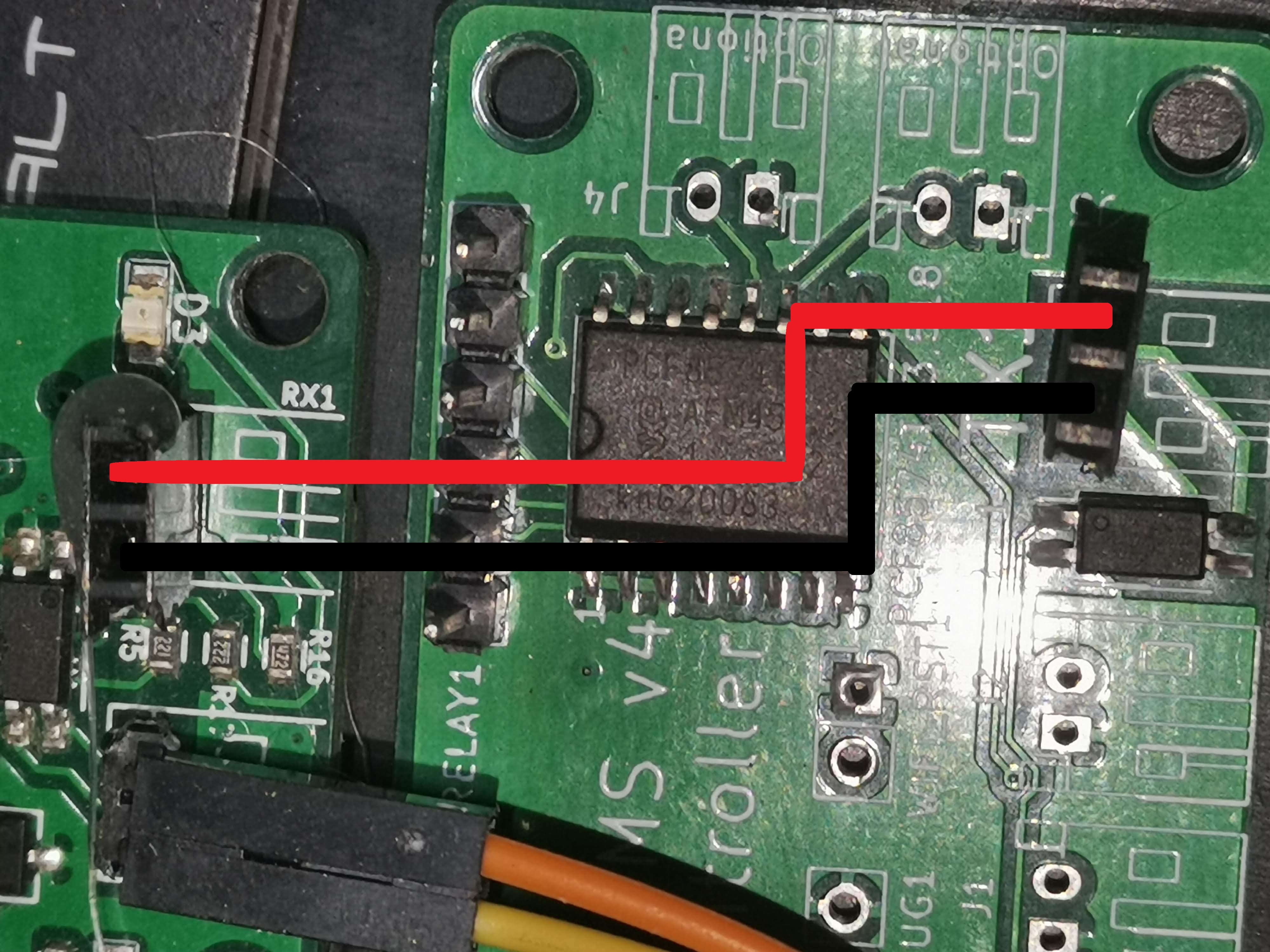
 yes, red cable at the black terminal and black cable at the cream colour…
I should be able to manage that
Simple hardware debug procedure…
-
With no modules connected to the controller, you should get the web page and lots of errors.
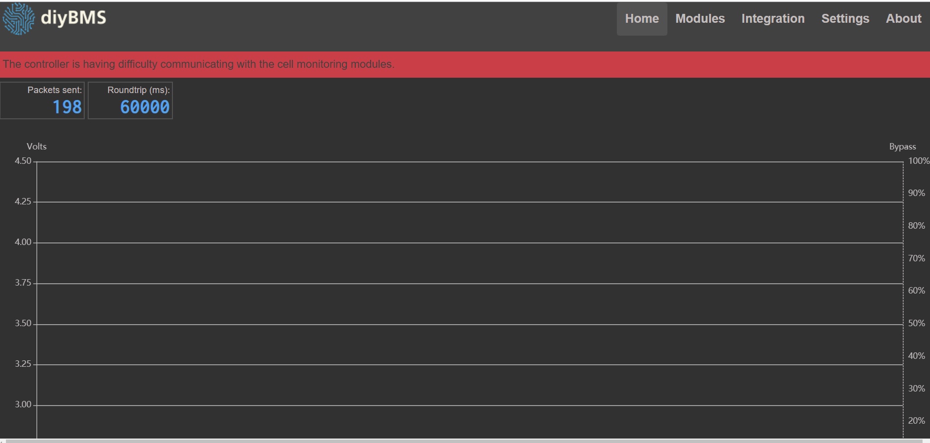
Nope, i see exactly what I see.
Even only the wemos shows what i normally see.
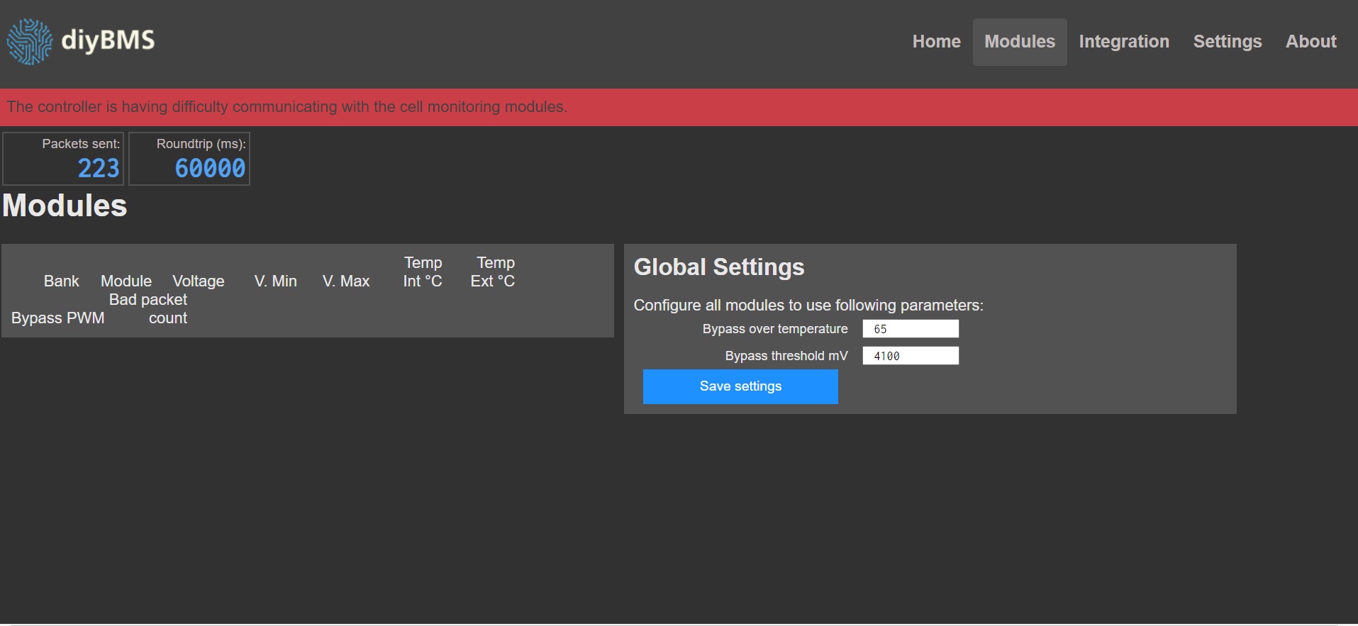
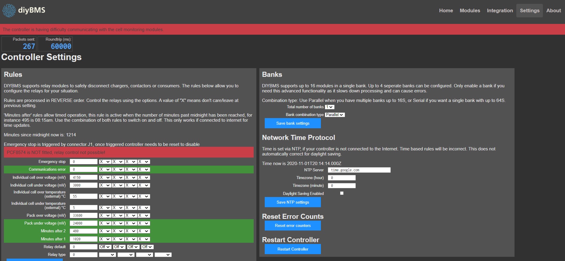
Only error i see is :PCF8574 is NOT fitted, relay control not possible! -
Build a temporary loop cable to connect the tx and rx together on the controller - you should get lots of “ignored” errors. This proves the controller is working and wired up.
-
Connect a module one at a time - they should just appear on the web interface one by one.
If any of the modules don’t show up, you have a soldering and/or programming issue with the module. When you upload don’t forget to use the “burn fuses” option on the ATTINY.
“burn fuses” option on the ATTINY. ???
Please explain
I tried again to program / flash the wemos.:
during the build / upload i get several “errors”:
#warning “Please include TimeLib.h, not Time.h. Future versions will remove Time.h” [-Wcpp]
and
‘SPIFFS’ is deprecated (declared at C:\Users\Frank.platformio\packages\framework-arduinoespressif8266\cores\esp8266/FS.h:269): SPIFFS has been deprecated. Please consider moving to LittleFS or other filesystems. [-Wdeprecated-declarations]
“Upload file system image” doesn’t work directly.
when i start it twice, or disconnect and reconnect the usb cable, it goes without problems
and again, with just only the wemos, i dont get any errors except communication time out
For some reason, I could only get the modules to appear if TX1 went to RX2 and vice versa down the chain… Strange.
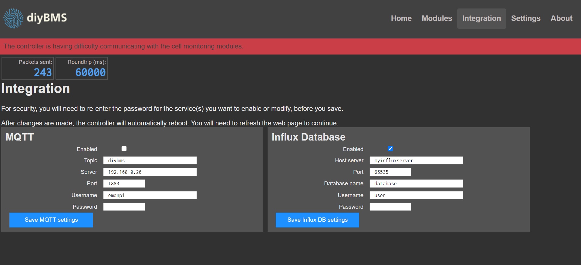
Is this the bunch of errors you talk about?
(see screen shots)
I have a spare laptop, and I’m going to make a fresh installation of visual and PlatformIO.
Internet is slow, that will take half a day.
I hope it’s corrupt installation of the software.
I’m running out of options here!
followed the steps on the videos, and don’t get any impressive errors.
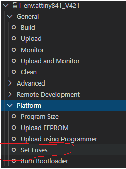
In platformio…
You shouldn’t need to do this step individually when programming the modules, however I have seen some instances where the fuses were not set correctly and that causes the modules to operate incorrectly - normally with comms issues. You run SET FUSES then use the “Upload using Programmer” option.
If you have got that far the WEMOS is programmed correctly - the red banner is the error message I was expecting.
Now try looping the TX and RX together on the controller (no modules connected) - you should then see “ignored” errors.