1 year after i bought all the stuff i finally decided to finish it, not easy to solder by hand as the pads could be a bit bigger, not easy to program as platformio is not intuitive at all but thanks to Stuart for this wonderful piece of engineering.
Thanks also to Colin Hickey, Adam Welch, Ricks Gadgets and gelisob for their great videos that explain it all from start to finish.
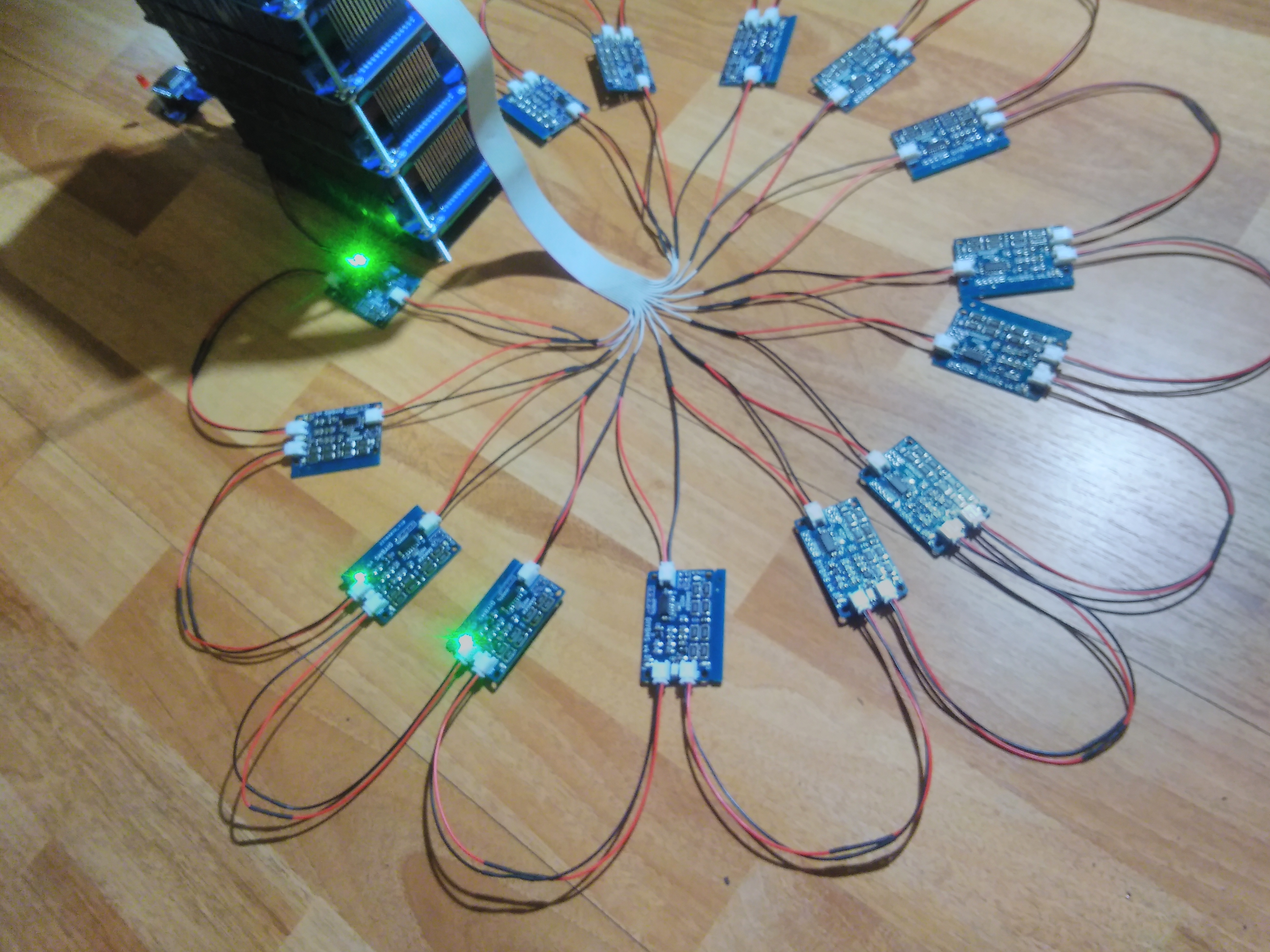
I had a susprise at first my battery was at 4.15v so all modules started to go red after 10s i had to program the voltage one by one 
1 Like
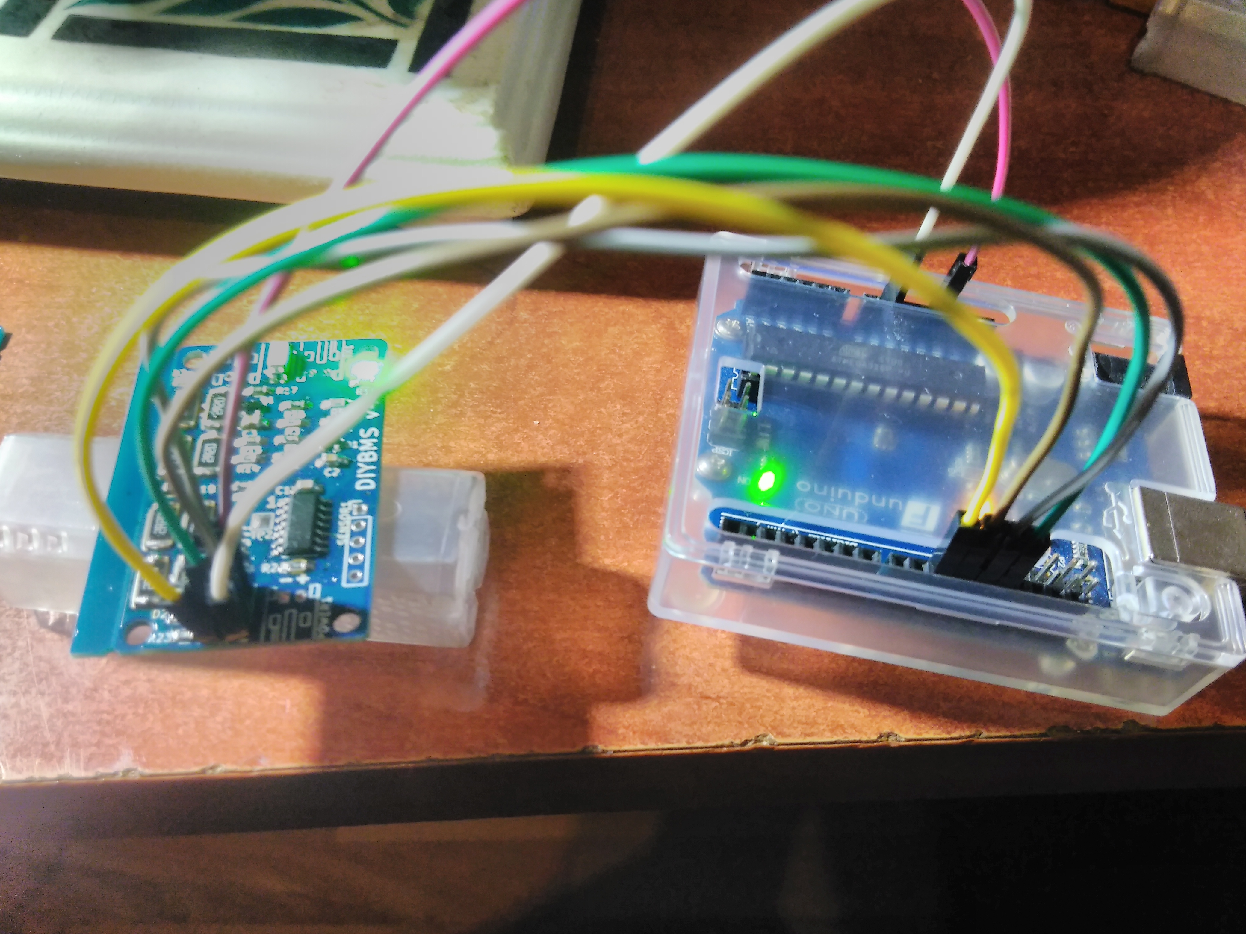
Very nice Marc!, Looks good and congrats to you for finishing it. It looks like you used an arduino in place of a USBASP module. Did you load the programming via arduino IDE app? Grats buddy I hope to be where you’re at soon!
yes as i saw on Ricks Gadgets video load with platformio
Hi Stuart, I did have 4,422 msec round trip at one stage but after a controller restart it has gone back to 60,000, I don’t know how or why this is?,I have gone to the dark theme software on the controller in a hope to be able to get my emonpi to read all the battery voltages, but still only getting the first 13 boards to read on the emonpi inputs, the rest are listed in the inputs, but do not record any data.
The controller starts at 60,000 but after the first successful read of all the modules it should then show the actual round trip time - this is important as it uses this value to determine if a module has gone offline/fault.
Are you using the code from the GITHUB branch I mentioned previously ?
Glad you got it working!
Please ensure you use as short cables as possible - including the power connectors, ideally these are connected directly to the battery terminals on each series cell.
I have just worked out my comms length cabling, adding each pair of comms cabling into a single strand of cabling it works out to be about 8,400 mm long, might look at seeing how short i can go, just wondering if I twist the comms cabling, like network cabling so as not to get crosstalk between the pairs?
The comms isn’t too much of a problem at that length, definitely twist it though. You need power wires as short as possible - don’t forget you will be pulling nearly 1amp down those wires.
1 Like
2 posts were split to a new topic: DIYBMS v4 ebay sellters
Hi!
What’s the easiest way to upload to emoncms using url + apikey? Anyone using this method?
Thank you!
Integration → MQTT
before: firmware “HysteresisRules” - verified!
Use the Mqtt settings
OK never mind. I have emoncms running on a commercial hosting service and thought MQTT is not available. But there seems to be a server running. Probably will get it running this way.
Thank you!
Hi,
Did you ever manage to work out what was going on here?
I get exactly the same thing.
taumarc
yeah i was not using the correct branch, you have to download master branch, but just watch the youtube video of how to compile it as its now changed
Roundtrip 356 (ms) and no packets lost with 20cm or a roll of wire, so comunication error have to always be because of not using shielded cable right? (just testing)

@stuart is there a place i can read about following ? Such as:
- What are the best settings for LiFePo4 ?
- How should one configure the relays ?
- What should the bypass settings be set to ? I guess this is connected to 1.
- Explain more in details and with some examples the rules. I know there is a video but i feel it doesn’t dive enough in the details.
- What is Load resistance ? What is mV per ADC reading ? Do i need to change any of these ?
also i think it would be great with more info on :
- The rountrip, what is best practice ? When is there a potential issue ?
- How long should the cables be ?
- Gauge of cable ?
- Which cable should be twisted ?
- Some explanation of banks concept again with some examples.
- Troubleshooting.
Maybe beyond specific diyBMS but i would really like to know in general how diyBMS plays a role in a solar installation, for example how does the BMS ensure the charger in the inverter is shut off and i what cases does it do that ? How does that play with the bypass ? The bypass works when the BMS shuts down the inverter/charger until the values of the cell are down to the required values ? ← i think all of this is general school material understanding the concept and i am not sure i understand fully the overall picture. I am just imagining how it may work.
Hi @donnib, theres a lot of topics covered in the post.
As you can imagine, there are so many combinations and variables that affect the operation of the BMS and a lot of the depends on what you are building and what type of cells you brought/use.
Some is trial and error, but a lot must be taken from the data sheets of the battery/cells.
It would be impractical for me to give guidance and possibly dangerous to recommend settings which could cause fire or worse.
Any BMS system should be seen as a last resort item - its there to stop nasty things happening. The charger and inverter should be controllable from the BMS so if needed it can shut them down, but the charger and inverter should be intelligent enough to know what battery chemistry and voltages to charge/discharge to/from.
The BMS isn’t a “system controller” its job is purely to prevent damage to the battery packs.
1 Like
@stuart yes i understand but i guess guidance could be given and more information that users can use to find the information they need. For me examples are the best solution so things like that because users can understand the concept and relate that to their own solution. You can always just write disclaimers. For example if you have a battery like X then you would do X which means X because X happens. Let’s see what happens when one cell get’s to X, now we can see the relay switches and charger does X until X happens… i guess you get the idea.