I already have a system with Pylontech style battery that we usually use in telecom UPS systems. Unfortunately these are 15s@48V, but that isn’t a big problem for my MPPSolar Inverters.
I would just go and buy flat aluminium extrusions. Cut them to length and drill the needed holes if you have the possibility at your site.
It’s all in this thread including the link to Jau’s work (26 Feb) which has all the files you need for JLCPCB.
Sadly they don’t always have all the components. In my case the diode, the thermistor and attiny were unavailable, the diodes are available at LCSC again now. JLCPCB now install JST connectors! For the shunt and new controller I just bought the bare boards and used Stuart’s new interactive BOM. The test shows the 4.4 board does work with the old controller with new software.
Thanks @Jau for the hard work and making it open source! and thanks @stuart for the original design and starting diyBMS!
I’m not expert but to make these board it looks like you open Jau files in EasyEDA and generate the gerber for your preferred PCB maker. I believe JLCPCB and EasyEDA are the same company so it should be easy
Looking forward to getting my cells and building out some boards!
edit: Looks like the Lishen_4_2 design has a DRC error with the text. Hopefully @Jau shares the v4.4 soon!
Thank you very much for the work to you all.
I had been few months watching carefully about your project.
As soon as I have some leverage to start mine, I will post something more productive.
I am pretty much the same place. I’m ready to have a bms that I can rely on and understand, and see so to speak. But my experience with this stuff it’s pretty old like me and so quite honestly I wouldn’t mind doing a multiple order if that would be worth someone’s time and save people money.
Honestly, the process for making the boards certainly doesn’t look very complicated as long as all the gears are moving. Some gears we can’t control or anticipate changes well, but overall pretty straightforward. Anyway…
I’m starting up with a hundred watt Overkill bms just to get things going. Seems like it’s to the point now where the right inverter and some panels can generate a good amount of electricity pretty easily. I need to stick these batteries in the mix - oh, wait, everything just connects to the same $1K 5KW inverter -
Gotta get this first thing done. With or unfortunately without this very cool BMS system.
Today I have found this topic and decided to place an order of your stile modules for my 280Ah cells. Your design for these type of cells is great, thanks!
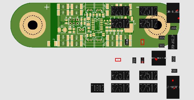
However, during order process I saw something strange.
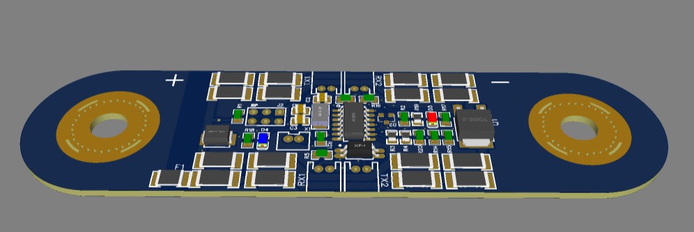
Instead of seeing a picture like this (from EasyEDA 3D):
I recently ordered some boards and they were assembled ok.
Mine also looked like yours in the preview
Struggling to find the parts for the controller though
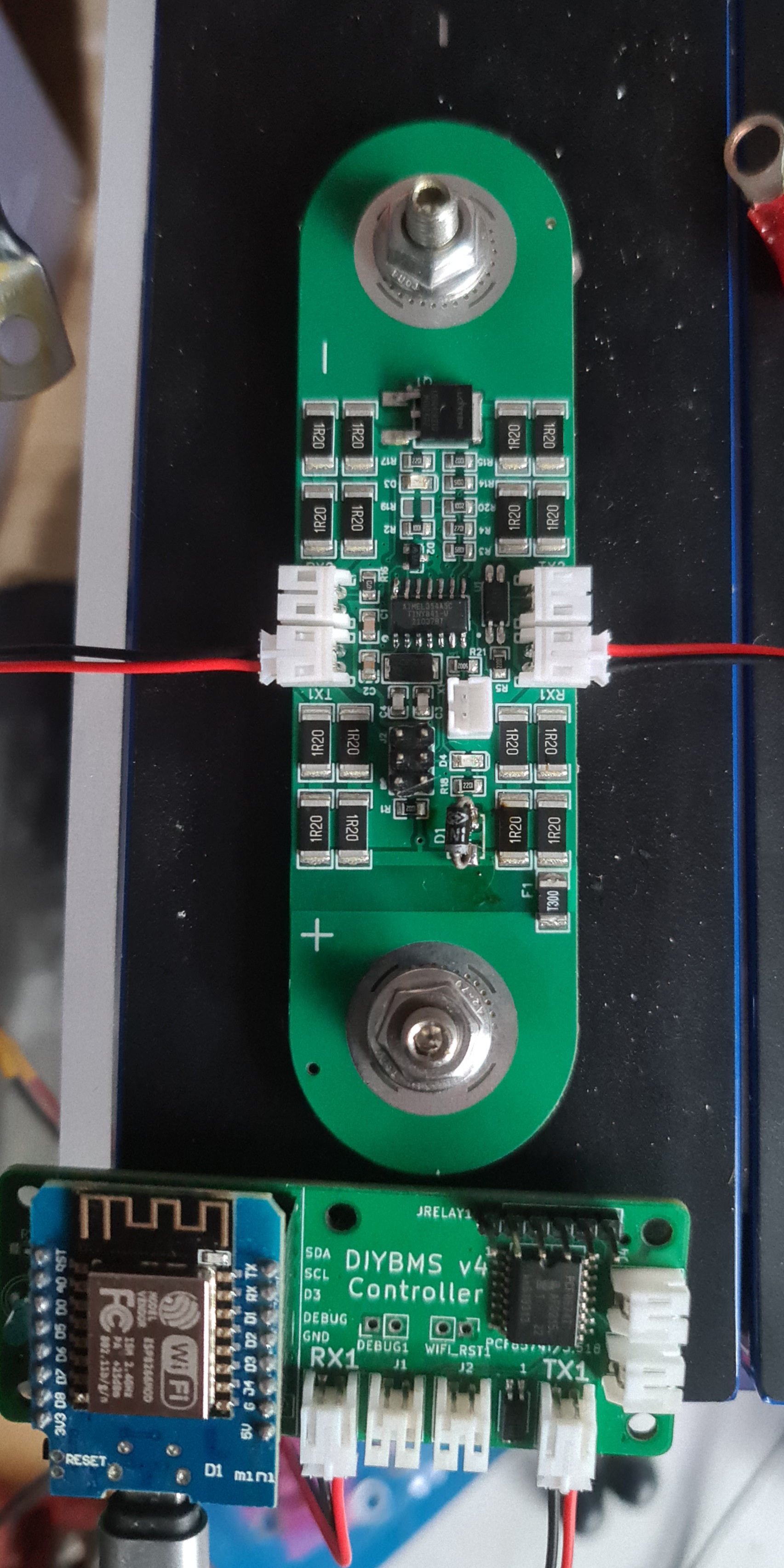
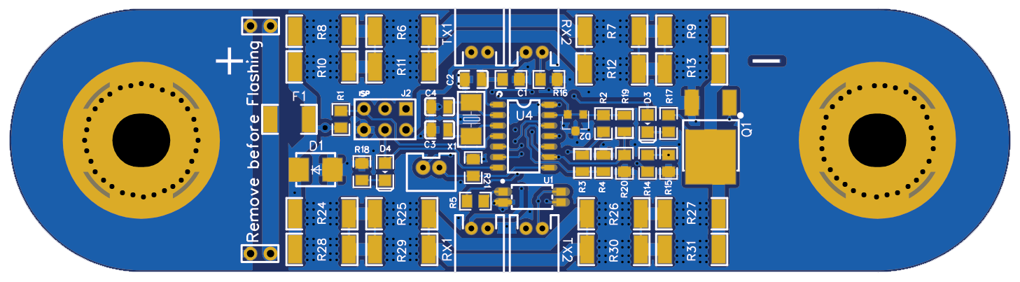
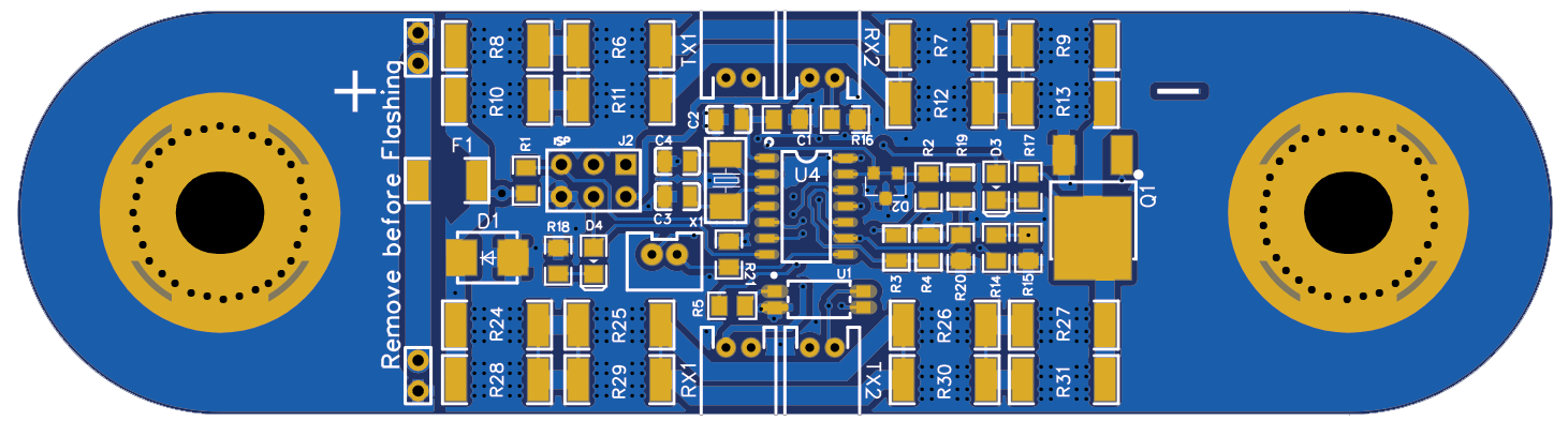
One thing I’d suggest if you are getting some boards made would be to add a jumper to disconnect the cell to allow for software updates without having to dismantle the whole battery as I’ve just done. Probably only need to disconnect the negative supply? It’d be great if this was in kicad and github with the other boards.
something like this maybe?
shifted F1 to the centre and pushed it away from the terminal and fitted two jumpers either side (only need to populate one)
it’s on the positive though, any reason why it’s better on the negative?