You are totally right a bit of airflow will get rid of heat fast. Still I would like to advise you to do some calculations on the heatsink and airflow needed to get rid of the heat produced by only 1 monitor board dissipating 23watts.
Heat sink size calculator for Tcase max use 65 as this is the max temp for the board and resistors.
1 Like
3 posts were split to a new topic: Dangers of Lithium/LifePO Batteries
I’m seeing some recent discussion of increasing the balancing current–is this really that important? If I look at a commercial BMS (e.g., the ubiquitous Daly), I see that its balance current is only 30 mA, even for models as large as 500A. The diyBMS, in its stock configuration, manages 40x the balance current. Surely this would be sufficient?
For new, well matched grade A cells a low balance current is more than sufficient. For second hand, grade B, bottom balanced or mismatched cells then a higher balance current is justified.
Thats a lot of heat!
Also - why are there two TX/RX JST sockets?
I believe it is so the boards can be used either way around (typical parallel vs series cell arrangements) and still be connected cleanly to the adjacent boards.
A lot of heat indeed! A good test of the PID algorithm! Heatsinks and forced air will likely be required.
Blaine nailed it. Only one each of the Tx/Rx sockets would be used, depending on cell arrangement.
Are you ok with your name and the project name/version being on the silkscreen? Any critique appreciated!
Perhaps change the silkscreen to something like…
“Based on diybms design by Stuart Pittaway”
Just to make it clear that it’s not something I’ve designed directly.
Will do, thanks for the input!
Why not place a 10W 2,7Ohm cement resistor over the PCB (like v3.0).
Lifepo4 cut Off is 3,65V means 1,35A @ 2,7 Ohm max. thats 5Watts.
And the Heat is not transfered to the PCB.
For me, the cost difference and susceptibility to vibration damage led me to stick with smd resistors.
1 Like
Looking forward to your controller, that woud ease installation by miles.
One thing i would like to bring up: maybe no all will have the chance to install active cooling or install it in a close box. May there be a chance to have a solderbridge to steer the restistors/balancing current?
Excellent points. Since JLCPCB will only populate one side of the board, it will be up to the end user to add resistors to the backside if they desire higher balance current. If heat sinks or fans are not used, Stuart’s pwm logic will modulate balancing to whatever board temperature you deem acceptable.
1 Like
Hey Billy_Boes,
How are you getting on? I would like to help, but i guess i’m pretty useless…
Any chance you’ve had a chance to try out the boards? I am willing to give untested boards a shot, too.
1 Like
I’m also interested in trying out the boards. I have soldering and software experience I can offer.
Thanks
–
Steve
1 Like
Sorry @all for waiting… Had to change my Job recently and got stressed out. I will test the new design tomorrow. Stay tuned 
3 Likes
Got V4.4 R1 working. Had to change some small routing problems but now it should be good to go. I will upload the Gerber to my GitHub in a few days and release them as soon as i know the design is stable.
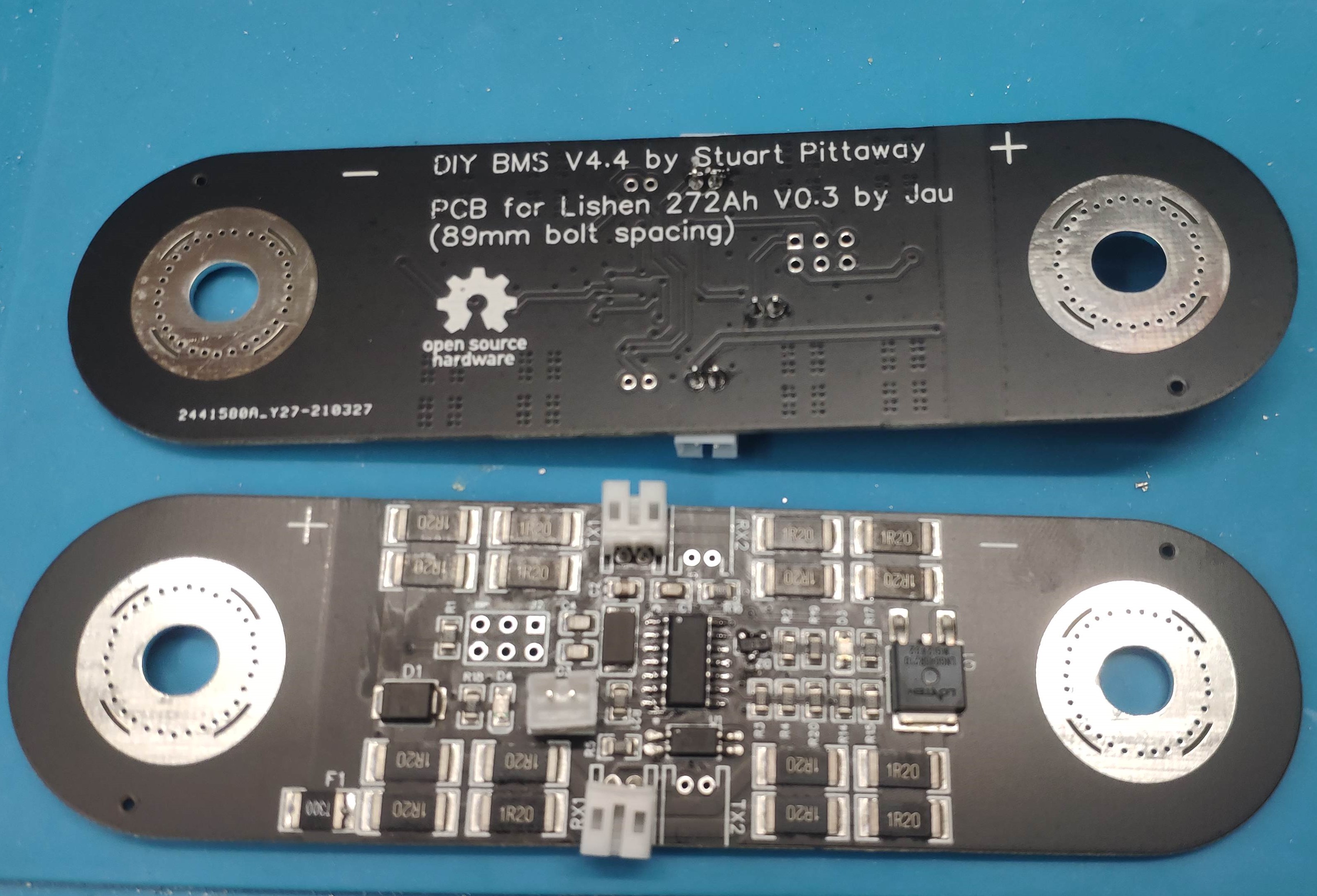
This is the Old version with only one connector each side. Here you can clearly see the problem with the crossed wires.
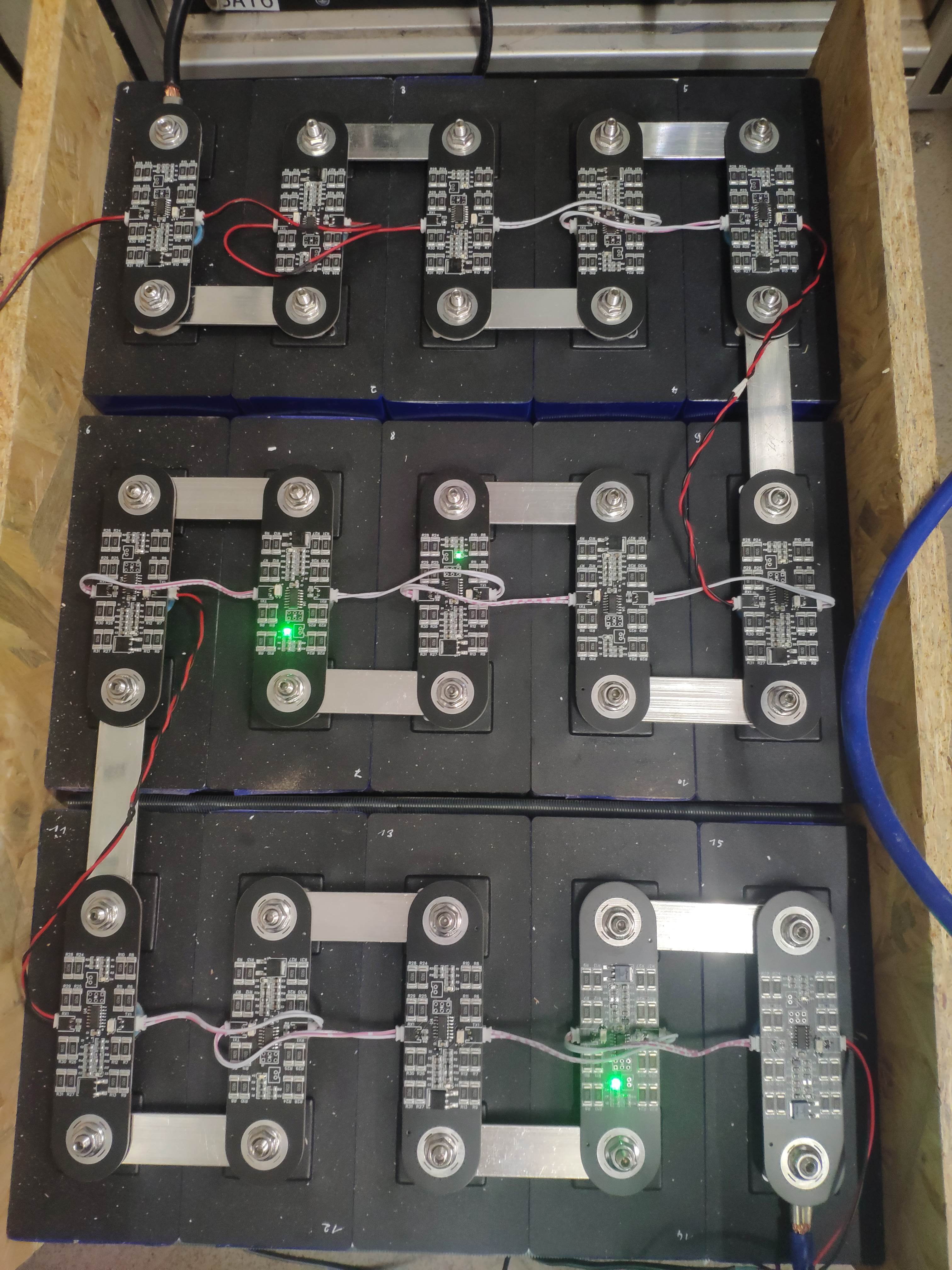
The new version is way more tidy, maybe I’m going to shorten the jumper wires too. Ext resistor should be an 50k B3950. Im using a foil type because I’m going to stick them on the side of each block.
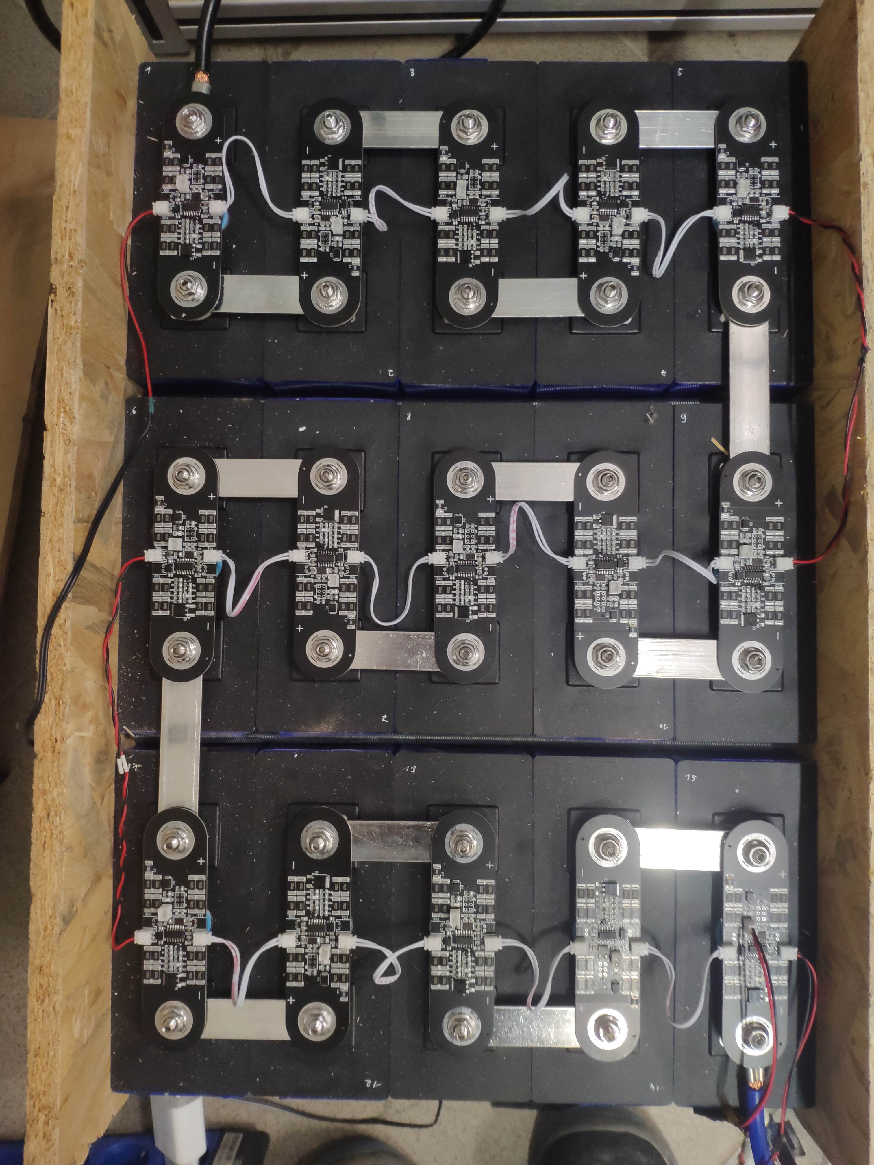
Now i need to figure out how to nicely build them in to 19" Cases. And how to compress the cells good enought in the tide space.
10 Likes
Looks awesome Fabian!
Cool. Thanks for your work on this.
Anyone know where I can get aluminum bus bars for my EVEs?
Fabian, I see 15 batteries. I’ll use 16/48V in my setup here in the US. May I ask what are yours set up for?
Thanks.
–
Steve