I would like to be able to find the gerber file of v4.40 to be able to order the modules from JLCPCB
Thanks
[DIYBMS_Lishen_v1.4_VB.zip|attachment]
not quite sure on the policy, hope I’m not doing anything wrong…
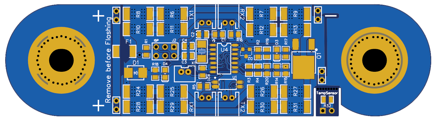
that’s @Jau work with two additions:
A. jumper to disconnect board for programming without having to physically remove it (as suggested by @Andrew_Congdon a week ago)
B. added the breakout thermistor that hopefully can be stuck on the side of the prismatic cell
normal disclaimers apply, haven’t built and tried it!
EDIT: found some issues on the PCB, don’t do anything with that!
V.
Just remember that all the current for balancing will be going through the 1 or 2 jumpers. Normally they should be considered to be rated for about 1a at max each.
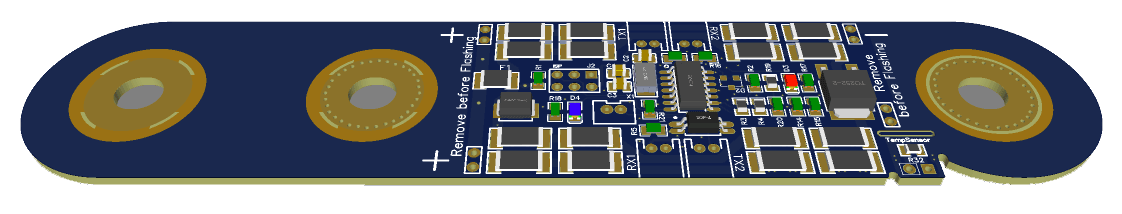
My thinking was… if you have a 16s battery and you consider the top cell the positive might be 53V and the negative ~50V. This made me think you only need to disconnect the negative terminal but I guess you really need to disconnect both? I’ve converted the project to kicad and added a jumper. The boards are on their way from JLCPCB so I can test them. As the jumper is only going to see 1A at 3.5V I think it will be adequate but of course can be modified if someone has a better idea.
not an el.engineer, have to admit I lost you there…
I expect the reprogramming will take place on a notebook with a usb connection to the whatever board which will be mounted on the modules. So I assumed voltages will be floating no common ground between the notebook and the module meaning just opening the circuit to the battery terminals should be enough. I expect that both connection cables to the neighbouring modules will be also disconnected.
am I missing something?
anyway easy to add a couple of jumpers on the minus side as well!
Final Q, where would you fit the external thermistor on the prismatic cell?
I need 8S expect to have 4 and 4 in one squarish box. With the cells flipping positives and the need to compress them (probably use thick plywood and through bolts) means on each cell there’s going to be only one side accessible. Only the one will be by the positive the next one by the negative pole.
Is that OK or values will be skewed?
IOW, is this extra thermistor going to be of any use or is it waste of time?
cheers
V.
In the future you’d like to be able to programme the cell modules with the controllers built in programmer.
That’s the issue with the common ground.
You’re trying to avoid dismantling the battery just to reprogramme the cells which you’d still need to do with a laptop programmer if you can’t disconnect the cell from the module.
The i2c should be isolated so you shouldn’t need to disconnect them AFAIK.
My ambient temp is 10-40C and that is the more relevant temp you want to measure with these cells and take action if the cells get too hot or cold. I’m lucky that’s not likely to be an issue for me at my location.
I’ve put my cells in an acrylic box with holes cut for ventilation and a couple of NTC with similar properties to the SMD device and looked for indicative locations in the box.
thanks Andrew,
well initial plan was to put this EVE280Ah 8S in the engine room next to the trojan FLA bank. Temps easily reach 45-50 when engines are running for a few hours in the summer, so looks like I’ll relocate them above under the salon sofa.
Haven’t looked at the code yet, but if you have two ntc s one onboard the module and one stuck on the side of the prismatic cell, top one stays under 40, side one goes up (and due to air circulation the one onboard the module hasn’t picked that up yet) do you have different policies for them, or same thing like:
if either or ntc is over 45 do this
do you know?
attaching latest attempt with jumpers on both sides:
cheers
V.
After all. Idea to make a carrier PCB with 440 module above it, was not so bad IMHO.
1 Like
According to cell specs charge temp 0-55, discharge temp -20-55.
You’re not worried about module temp since the PWM code will limit the discharge rate according to temp.
I was suggesting you don’t need an external NTC per module, just a couple per battery.
Someone else was reporting JLCPCB are now charging extra for the NTC board.
Sounds like you might want to consider forced cooling of the battery case controlled by the external temp sensors. The old controller can do that too.
yep, just not sure how the temp of a discharging battery develops.
Saw that mentioned, however I got my designs in JLCPCB and they don’t charge anything extra for the breakout NTC board, so will probably keep it, extra cost is the extra NTC chip, dunno few cents…
Being on a boat, not particularly keen on having forced salty wet air moving around tbh.
I guess it’s a suck it and see situation, hence having the breakouts, may use them may not.
Planning on a fairly conservative charge/discharge plan anyway since I manage to survive with much less than 100Ah on a daily rate in the summer.
My main issue is getting the attiny841-ssu chips (Farnell has them!) and building the ESP32 controller board, that is much harder atm and I’d really like to test the victron canbus connectivity to a rpi. May have to spent a few days and nights working on it, impossible without the board though 
cheers
V.
well, even my modified version of this board was flagged as being two boards in one design by JLC staff. 11usd more for 10boards. Just a warning, could remove all perforation but then you should need a dremmel to carefully cut them and doesn’t seem a v.safe way of going ahead with this.
for the record, I just checked the specs of EVE280Ah cells I’ve ordered, and post spacing is 123mm and not 89mm!!!
V.smart considering 10boards shipped from JLCPCB today
this is how a 123mm spacing looks like!
will end up fabricating short stubs to bolt the one side of the pcb to the terminal.
V.
Mine that are Lishen 272 ah if they measure 89mm and now how will you do it, let’s hope they are worth it.
Greetings
will source some brass flat section and half a dozen brass studs, cut/drill/weld and create small connectors…
unless someone else wants them and I order new ones. we shall see, first I need to get them, solder the ATtiny and test them all, then we’ll see. Batteries wont be here before Jan anyway
ok we are in contact
I have just looked at the technical sheet of the EVE 280ah batteries and I see that the distance between terminals is 90mm I send you the fileEVE_280Ah_DataSheet.pdf (685.7 KB)
solved by going a size up and getting the 304Ah version of EVE cells which have 90mm terminal distance 
only two months now for delivery (fingers crossed!)
Let’s hope you’re lucky now, do you already have the modules?
not yet, FedEx says Wed (currently in BE, should be ok)
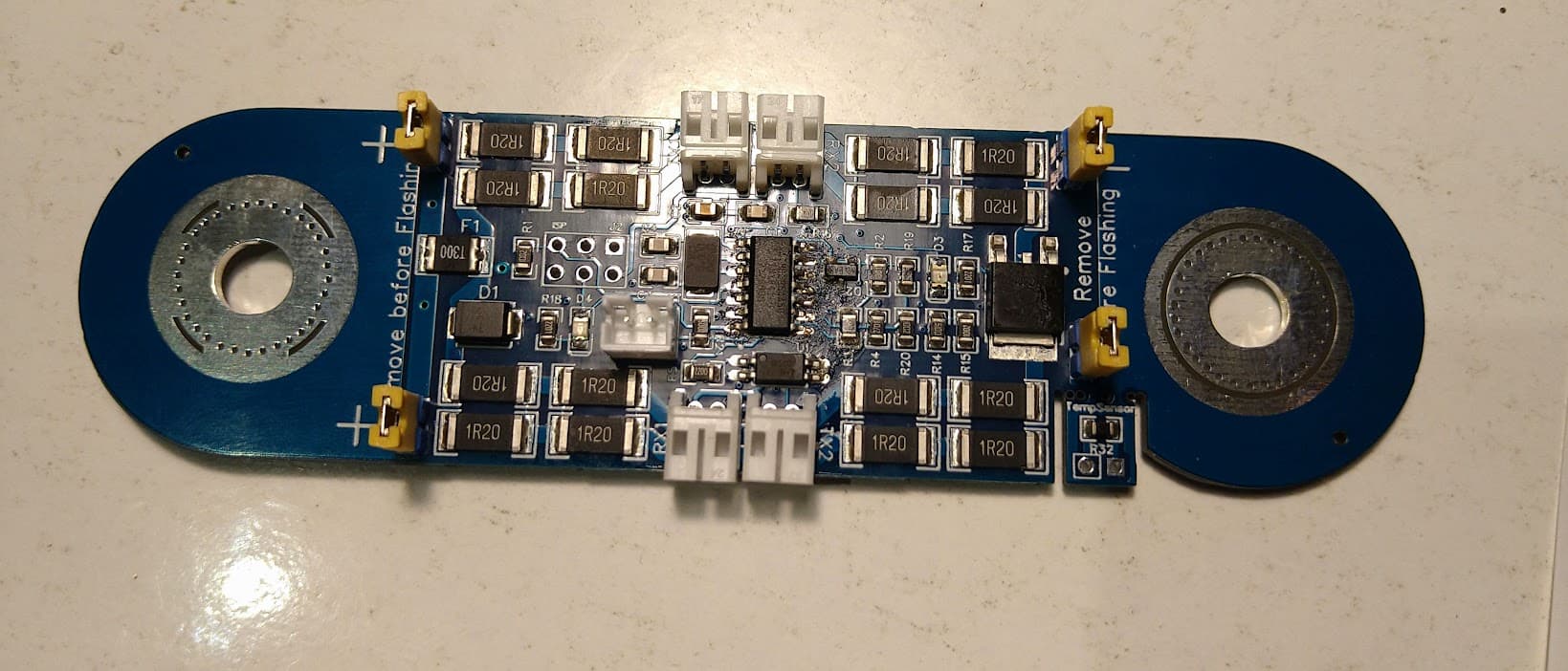
boards arrived, cannot claim that i’ve done a stellar job fitting the ATtiny chip using solder paste and hot air for the first time in my life, but it looks okish. the right hand side looks v.bad, it isn’t it’s the lighting:
Hope tomorrow to have a couple of them and a controller board ready to test coms. Will report when it’s working.
Mind PCB is really hard almost impossible to cut the thermistor along the preforation. Much better the newer version with a cut along the length of the PCB, and two groves that a dremel will fit and cut across.
cheers
V.
1 Like