If you use my design there is no concerns about clearance to the busbars. The Heatsinks should work fine. Did you allready order one of my designs?
The Heatsinks should work fine. Did you allready order one of my designs?
No, I was taking measurements from your 4.2 project posting.
I have an 18650 pack working with 4.21 boards.
Off topic, do the 4.4 boards work with the previous gen controllers I have left over?
My terminals, measured between the M6 threads, are 90 mm apart center-to-center.
The terminals themselves are 16 mm in diameter. Aluminum unfortunately. Thread depth is a scant 8 mm.
I suppose the contact to the terminals from your board is copper. I’m concerned about that a bit based on other problems I’ve seen around online. Not sure if any of you folks have any ideas about that.
Thanks again.
–
Steve
Wait - I guess the boards sit on top of the bus bars? Oops. But then I guess the bus bars connect to the boards. The one picture I saw looked like the bus bars were aluminum, which I’m thinking of using. What about the connection from the bus bars to the board?
My bus bars are nickel plated copper strips. The PCB usually are also Tin plated from the levelling process. So in my case aluminium (terminals) <-> nickel (bus bar) <-> Tin (PCB). Didn’t know there is a problem with the aluminium terminals and copper bus bars.
As i know there shouldn’t be a problem with aluminium to nickel in therms of corrosion
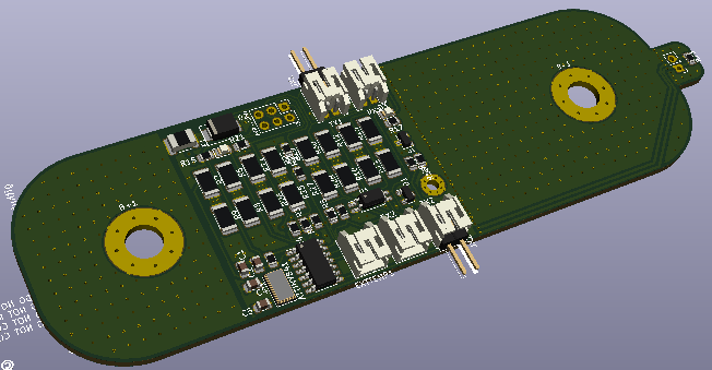
Reading back through this thread, the goals for a universal cell-mounted balance board are:
- Based on latest schematic V4.4
- Rx/Tx ports on both edges of board for cleaner wiring
- Snap-off external temperature sensor
- 90mm post spacing for 272-280mAh LFP cells
- Negative pigtail option for cells with other post spacing
- Burden resistor arrangement to allow a single heatsink
- Anything I missed?
Based on these goals, here’s a revised conceptual design. Constructive criticism appreciated!
1 Like
Apparently the 4.4 standard boards are achieving 1.2A equalisation currents without heatsink.
That sounds enough for these big batteries?
The goal of having a single heatsink might be a cost saving or the simple stick on heatsinks I showed above are probably sufficient?
The snap-off external temp sensor is required to measure the ambient temp so charging can be controlled to the supported temp range for these cells, particularly the low temps that won’t occur for me 
Monitoring cell temps in charging is less likely to be needed AFAIK?
I’ve seen some problems with the bus bars that come with the batteries, which I believe are nickel plated copper. They are hard to keep Seated on to the aluminum terminals. I’m not sure how the different metals interact but it seems like thick aluminum bus bars would be a good idea especially if you could make a gas-tight connection to the terminals with an aluminum serrated lock washer or something like that (guessing) pressed between the terminal and the bus bar. The set screw wouldn’t move but would be all the way down into the threads and held with a hex wrench while you cranked down a nut to press the bus bar on to the terminal. Does that sound crazy? Maybe others aren’t having this problem but I’ve seen it a couple times and I know that the aluminum terminals are a weakness as are the shallow M6 threads.
Thanks for listening I know that I’m kind of off topic here. I can move this to another thread if you guys want. Sure love the look and functionality of these cell-mounted controller/balance boards!
–
Steve
The 280 is a big battery how about additional resistors for faster balancing as the space is there
I agree that for significantly unbalanced cells, the current design would take days/weeks to balance. If you don’t have a “high cell voltage” rule set up to open the charging circuit, you run the risk of overcharging some cells.
The selected MOSFET will carry 5.7A of balance current, which would require 24 watts of burden load. Using 3/4W resistors in a 4s4p arrangement only gets us to 12W.
I see the three best options as:
-
use 1.5ohm 3/4w resistors in the 4s4p arrangement to give us 2.8A of burden current.
-
source higher wattage resistors (still studying this option)
-
increase resistor count (would increase board footprint, which I’m trying to avoid)
1 Like
Not trying to rush you, but I figured I’d chime in and say that I am excited to try your 4.4 design. My batteries are on the way and I will be ordering some boards from JLC as soon as you make them available.
Thank you for taking the time to create the design!
Maybe it is an idea to use a FET to burn energy instead of resistors. It might require a change in firmware, modifying the PWM duty cycle so the FET is partially opened.
My only input is to see about making one of the battery connection terminals a slot instead of a hole. The EVE 280ah cells are 89mm spacing IIRC, and so are the CATL 275ah cells. A slightly elongated hole would allow for both 89mm and 90mm cells to be used nicely.
Not a necessity, more of a wishlist option. Love the work that’s been done so far!
@firebat45
My ordered 4.4 Boards are in the mail and should arrive next week.
The holes in the PCB are slightly oval to fit batterys from 88-90mm. That is the biggest ovality that JLC accepts in my case to get it drilled before the plating process. Don’t ask me why but that is what my agent at JLC mentioned.
@Albert
Also thought about that. But i just wanted a plug and play Version from Stuards design and not bother about the software. That would mean that i have to fork the code from stuard every mayor update and modify it. The Resistors are cheap enough that i don’t care about that.
@Arden_King
That is the reason why i used Bigger and more resistors for a balancing current of 2.6A. At higher balancing currents the problem is the heat dissipation.
Normal there shouldn’t be electric corrosion between nickel and Aluminium. I think i will go with the provided bus bars and torque them with 5NM (should be more than enough) with a washer between Nut and PCB. But i also plan to just load them with max 80A.
In future I would maybe go for 10x30mm AL bus bars. But atm I’m to lazy to manufacture them for that project by hand.
1 Like
Another option would be a have separate resistor board that has a direct cabling to the battery that has also has the mosfet onboard to do the switching and a separate board for the monitoring with a link to fire the mosfet resistor board, this way you keep the heat problem away from the monitoring board, these resistor boards can be made any capacity or doubled up on some bigger battery bank to help balancing, it will also eliminate voltage variations on the existing type of boards caused by the load of the mosfet turning off and on
1 Like
This is a very interesting concept, giving me some ideas to make better use of the spare real estate on the negative half of the board. I’ll work on this over the weekend.
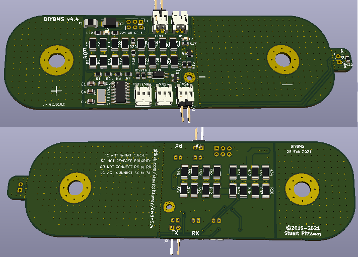
Another idea to consider, which is a combination of options 1 & 3 above. Load resistors have been changed from 3.3ohm to 1.5ohm with another 16 load resistors on the back of the board, bringing the total balance current & power to 5.6A & 23.5W @ 4.2V.
@Billy_Boes Your design is looking really nice but I have some concerns. You raise the amount of energy the circuit can handle on the same surface size, that means it will get hotter. Where does all that heat have to go? And something I don’t know but also concerns me is that this heat is produced close to the top of the cell. These cells can handle for sure some heat but is it OK to heat them up unevenly? Also think of the overpressure valve that is just below it.
I like the idea @Ross came with a separate board with resistors and a FET that you can connect to the board on the cell. Such a board you can place away from the cell for example on a heat sink. This also has the advantage of making the design scaleable you can connect to your design resistor boards that can handle different amounts of energy. So a user can select a board with resistors that fits his balancing needs and can still use the same cell monitor board.
1 Like
Albert,
Thanks for the feedback! I agree the additional heat generated will require either passive cooling via heatsink(s), active cooling via forced air or both. I’ve been testing different heat dissipation techniques with Stuart’s board design, and have been surprised how little air movement is required to keep the board below 65degC during balancing, even without a heatsink. The latest rules allow triggering a relay for the fan if/when the onboard thermistor rises above setpoint.
Regarding Ross’ idea to distance the balancing circuit from the battery, I feel that Stuart’s existing board design accomplishes that. I don’t believe there’s any advantage to splitting the module components into several PCBs. This greatly increases the cost without benefit.
I do, however, really like the idea of modular resistor banks, allowing the user to customize their balance current. Still thinking about how to best accomplish this.