Is the current most updated version. It is not tested because i changed the design to stuards V4.21.
Normally there should be everything OK because the known problems are already fixed at that design.
As soon as the new controller version is released by Stuard i will also order and test my new design.
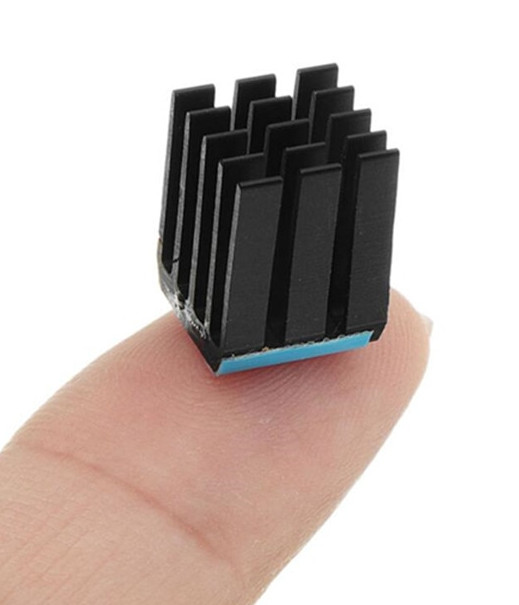
Yeah, you need to change some parts with only the 67mm spacing. I would recommend to change all parts from 0806 to 0604 and also reduce the power resistors from 16 to only 8 for a 1.3A balancing current. Should be more than enough for 50Ah cells and if you are not cooling them with an extra heatsink they will reach 60°C very fast anyway.
I’m still waiting for my boards to arrive but I did not make significant changes… I did replace the one temp sensor resistor. Will update when I have something new as well but guessing will have to make the changes Jau already had to
@Billy_Boes These technically should work with the new controller board as well… the “circuit” boards attached to the cells themselves are supposed to be the same for either controller board.
Add one more interested party. I too have the Lishen 272Ah cells (64 of them.). I am hoping to get one of the new controller boards atanisoft is preparing for those in NA area. Adding these would make the project that much easier.
The actual design should work. But i want to update it to the new V4.4 soon and also make a second design because the communication connector is on the wrong side for every second battery.I planed to make a PCB with two mirrored designs with a break point. That will make the assembly by jlc way cheaper.
If anyone else has an idea how to arrange the com ports that they work for both orientations let me know.
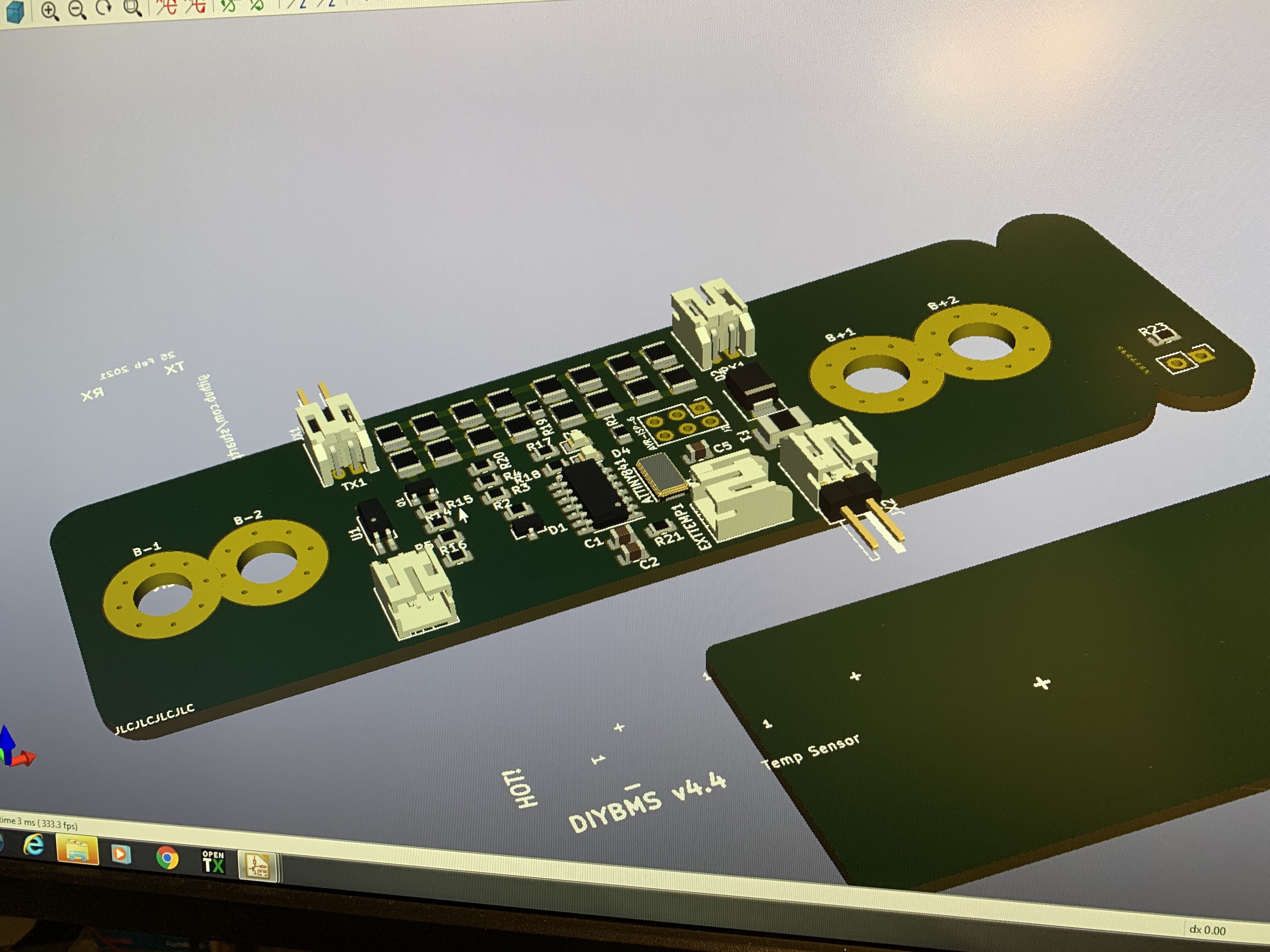
Looking at the 4.4 design with the break for the external temp sensor…
I’ve used the external sensor on other battery packs but I’m assuming with the prismatic cells you just want the sensor on board near a terminal? So is another sensor required? Or put a sensor at each end?
Is there any reason not to make an odd and even board with the com ports swapped?
Hy,
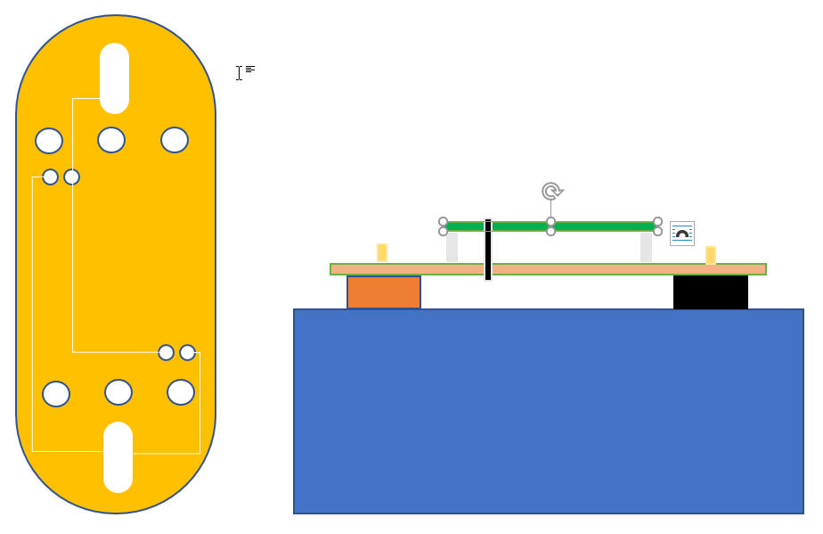
I´m not familiar with PCB generation but I like the Idea from a Adapter PCB to stick Stuart´s v4.4 Module on a LiFePo4 Prismatic cell.
I made a example of what I think about … the Adapter can turn for + and - so that the Original v4.4 is always at same orientation.
Maybe it´s possible to contact also “Ext. Temp” to the Adapter ?
I thought one advantage of boards specific to this cell size was the ability to use larger resistors for greater balance current for these now up to 310Ah cells? The odd/even board idea means you could also add heatsinks on top. Is balance current not an issue?
I think the problem will be that at least JLC will not plate the slotted holes because they will mfg them after the plating process.
I could make a gerber for that if you send me the step for your design. Hopefully i will find time to spend for the project this weekend.
The first design is running since 2 weeks on my test battery without any problems.
The specific design with odd and even is because it looks more tidied up.
I have to build at least 10 packs á 15 cells for me and some friends so they should at least look nice
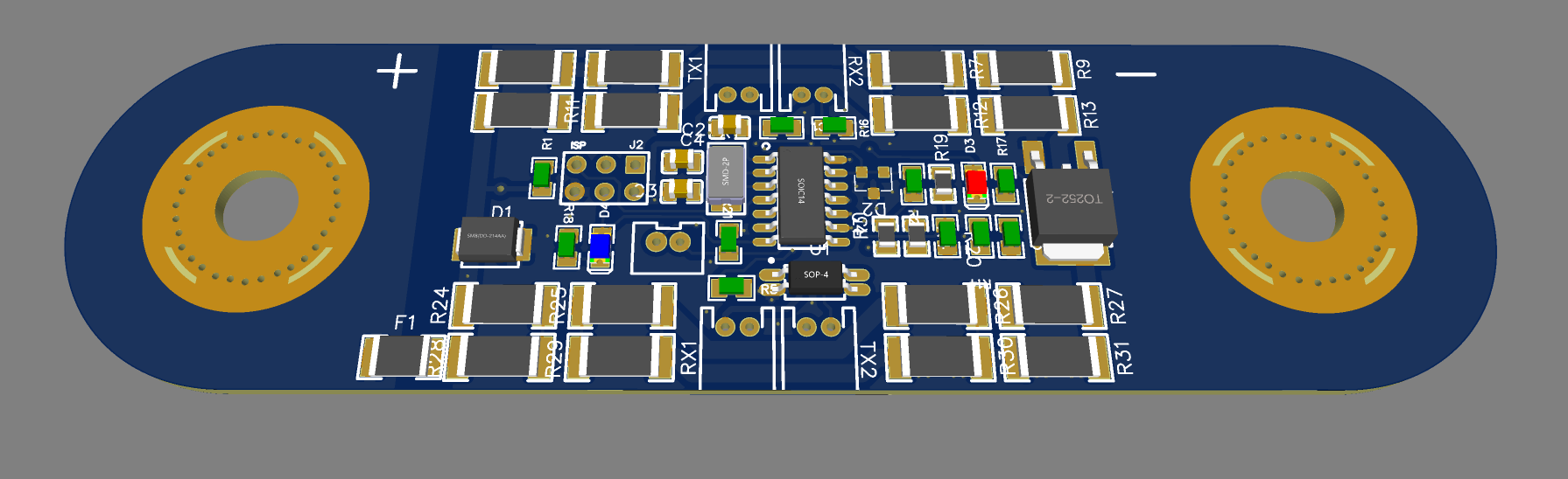
Jau, duplicating & moving the Rx/Tx connections to the ‘corners’ of the board is one solution. Traces are criss-crossed, so Rx pins are in the same place regardless of board orientation. Here’s a concept:
That is my new version.
We had the same Idea
There are now TX/RX connectors on both sides of the board. For Production i will maybe go for 0603 parts. The board is now quite crowded with the v4.4 Version. I will order the V4.4 tomorrow if there is nothing missing in the new design.
I don’t know what kind of cells and arrangement you are using. In my Cell arrangement your TX/RX connectors would collide with my busbars. At least the inner ones, and even with the outer holes i would not feel comfortable with a possible short circuit. That is one of the Main reasons why all my through hole components sitting in the middle.
You’re absolutely right regarding the potential interference between Bussbars and the PTH comms connections. I was more focused on keeping the balance resistors together to fit a single heat sink if needed.
Hmm regarding heat sink i also thought about flipping the board around and put a big heat sink on the backside. The only thing that then comes close to the busbars would be the FUSE and even that would still stay over 5mm away from the busbar. But I think my maximum balancing current is greater than your design? In my case i would need an heatsink that can radiate 9W.
I will test the heat sink on the backside when the new boards arrive. Thermal transfer through the board should be good enough because of the Stitching of the GND areas in the Area of the resistors.
What is the distance between the studs of your battery ? 89-90mm should work with my design. My pcb for the v4.4 are in production now. I would wait until i have tested them. If they are working I would release the design officially.
If you have the time and you can wait I would recommend to wait another 2 weeks until I have tested my design.