I guess that could work, but then we can’t see all the pretty blinking lights 
I guess then it would be a larger heatsink as well then, any idea on the part you would use and the cost? I for instance would require 34 of these heatsinks right now, more when I expand so that cost increases.
I also assume that with PWM modulation, the heat can be managed.
What is the purpose of the ± connections near the middle of the board?
You mean the connector next to the ISP? That is an JST XH socket for the external Temp resistor.
I did not choose an heatsink until now because i dont know if im goning to need them. As i know the firmware from Stuard includes PWM for the balancing circuit. Topbalancing of 280Ah LiFePO4 cells is quite difficult and i just will use the balancing function to equalize the cells from time to time.
how did your boards turn out? did you have them do the assebmly at the factory? i’d love an update as I really want to redo my system with a cleaner setup
Boards arrived yesterday. First impression they looking good. Haven’t had time to check them until now.
I will post some pics tomorrow or the next few days
i can’t hardly wait. My setup is working, but the wiring looks pretty messy if i’m being honest.
@Jau I also have some new 272Ah Lishen cells and would like to use your version so please let us know how your modification is working 
any updates on these new boards?
Sorry @all, had problems with our central heating system in the last few days. Had higher priority to fix that first. I will have a look for the PCB the next few days 
@Jau I went through the BOM and would be really helpful if could match the parts up with part # on JLCPCB. As someone else mentioned, most of the parts can’t be found based on the name in the BOM. I started going through it partly but am not confident enough to choose the right ones. One substitute I did match is the 25121WJ012JT4E should be 25121WF120KT4E.
My bad. I didn’t understand how to use EasyEDA… I was exporting the BOM from the PCB layout editor and not the schematic. When you export it from the schematic most of the parts match what is on JLCPCB 
Only 2 SMD parts that don’t match are:
- SDNT2012X473F4150FTF
- LM4040BIM3-2.0/NOPB, 2.048V, SOT-23-3
I ordered some of these boards to try out… I also replaced the SDNT2012X473F4150FTF with the version in the regular circuit (NCP15WB473F03RC) which required modifying the board slightly for the smaller part. The LM4040BIM3-2.0 and ATTINY I’ll have to purchase separately along with the through hole parts.
Hey David,
Yesterday i checked my design. Bad news, something is not working. Now its time to figuring out what the problem is. First problem is that the footprint for the opto is wrong. It is to small and i didn’t properly check it during layouting.
Flashing works but no communication. I will keep you updated.
Normal all part numbers should match with LSCS parts beside of the Voltage reference diode.
My Lishen cells also arrived yesterday after only 24 Working days. Ordered from Basen. As soon as the PCB is working i will check them with teh cells.
So, i already know that i flipped the footprints of the green and red LED and the connectors. I had to re-solder the LEDs and mounted the connectors of the com cables to the bottom. But i still have a problem because the modules don’t want to communicate with the controller. Tomorrow i will get my oszi and check the signals.
I did order the normal circuit as well in case there were issues with this new design. Also had to adjust a few things on the board that EasyEDA was complaining about… but don’t think it complained about those items…
My main issue was that in my test setup i used an old ESP with a firmware from February of 2020. Since then Stuard changed the communication protocol of the Controller. That did drive me crazy the last two days until i figured that out.
JLC didn’t complain anything with my order. What did they complain to you and what did you change?
There are more or less 4 Problems with the v0.1 of my board:
-
The LED’s are flipped → turn the LED around and resolder them
-
The TX/RX connectors are flipped → mount the first and last TX/RX of the chain on the bottom of the PCB
-
The R22 shouldn’t be soldered to the board. → desolder these
-
The Opto has the wrong footprint → squeeze legs together and resolder
The board is also based on the V4.0 design not on the V4.21 as mentioned on the Silkscreen.
I already fixed the known issues and also changed the board design to the newest 4.21 design from Stuard.
The GS Voltage of the Mosfet is 60mV at 2.6A current → 23mOhm Ron → Pmos = ~160mW what should be totally fine for this model.
1 Like
Jau, thank you for all of your work on this version! I have 64 50Ah lifepo4 cells in 16s 4p configuration, so the wiring would get quite messy if I used the original boards. I believe my cell terminals are a little closer together than 90mm, but need to confirm. Looking forward to your and David’s continued testing!
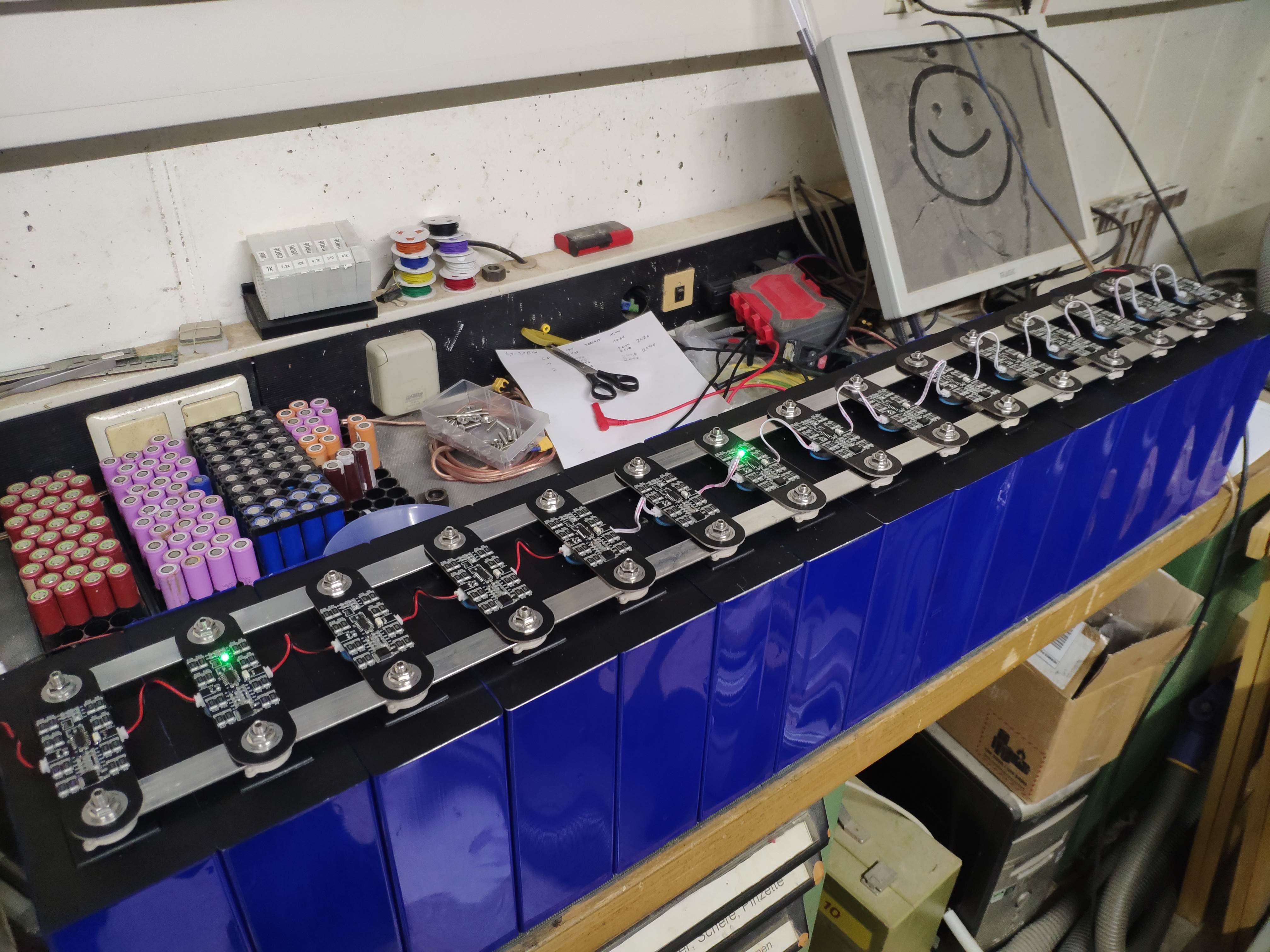
First 15 modules are working. Looking nice and clean.
If there is enough interest i could adjust the design for other spacing. Way smaller than ~80mm bolt spacing will be a problem because of the space for the traces and parts.
Still need to test the external temp sensor header, waiting for the parts to arrive.
3 Likes
Nice job! My terminal spacing is only 67mm, so I speculate the pcb will require significant modification. Are the OSH files your most recent version? If so, I’ll use them as a starting point.