I’m going to use some of the spare pins on the ESP module to drive outputs to the charger (perhaps via relays etc.) to switch charging off if needed
Collin, which fuse did you use?
Also is this tne right analog device. Is Sop-8 the same as soic-8?
New and original ADUM1250ARZ ADUM1250 1250ARZ SOP 8 10PCS|10pcs|originalpcs - AliExpress to clipboard
I recently orderred these.
Hi Jman, I went for these models. The adum1250 you’ve ordered looks to be the right one and slightly better value than the one i bought.
Fuse
I flashed my node mcu with the controller software succesfully
Great - don’t forget you don’t actually need the fuse - I’ve just used a piece of fuse wire soldered in at the moment!
Collin do you plan on merging your epfever mppt grafana dashboard with a dashboard for the diybms?
Hi Jman, yes definitely. I plan to try and integrate it nicely using the style Stuart has done. My skills aren’t up to the same as Stuarts though so I’ve created my own fork for now and shall integrate my code into that and then if it’s up to scratch it could be pulled into the main branch down the line if Stuart so wishes or i’ll merge in any enhancements Stuart does into his code into my fork. His code really is excellent.
I’ve three boards now so will crack on with the rest and get it hooked up to my powerbank soon. I know you’ve asked for where i’ve got the odd component and stuart has mentioned some of his source but it your interested i’ll provide a full set of links to the sources, which was mostly aliexpress.

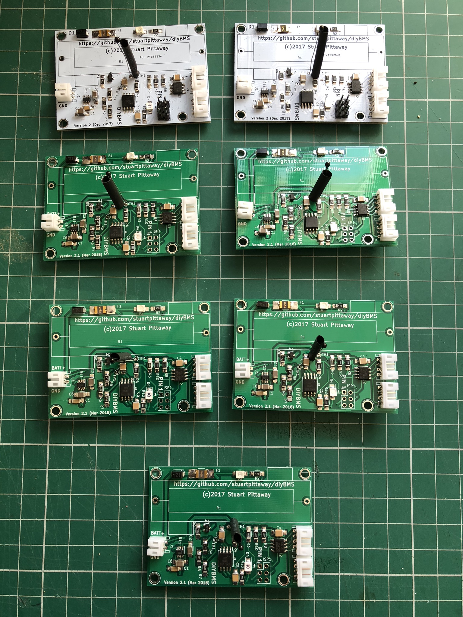
Looks neat.
Are you going to program the ISP using a POGO pin adapter? I did wonder about making an edge connector on the PCB to make things easier to work with.
No i just haven’t soldered on the header pins on the bottom 5 yet, need to do those and a bunch more of the interconnect cables.
I think I’m going to put the thermistors on the back of the board so it can be inserted between the batteries like adam welch did.
Yeah i meant to do that as well but forgot, so shall have to unsolder them and swap them around. Will use his mount as well if it fits ok on my packs. Just uploaded the code to the new boards i’ve done today and they have taken the code which is a good sign. I need to get my powerwall ready to accept them and can then start to hook things up.
How much storage do you have? My setup is 7s40p 2200mah Samsung 18650.
I have a 7s96p currently but it’s very much under utilised as i have no inverter so it’s powering my lighting in my garages and powers my robot lawnmower in the summer and not much more. I’m around 4.4Kwh.
My componenets from mouser arrived today. The reg710na are tiny!!!
Have you guys seen this bms board? I will be released in 2-3 months (approximately)
http://four-forty.com/shop/
I bought the 10k thermistors (±3%) by epcos on mouser for 34 cents each. I was wondering if there is a difference between them and the cheap ones from aliexpress with a “rated” ±1%.
lol i know i managed to hand solder the first board but won’t do that in a rush
Because I am not paralleling cells I only require 0.4A. Nowhere near what you will need.
Brian
It might work, it might not!
The thermistor is designed to detect a high temperature when the load resistor is on (50+ degrees), so it can be safely shut down. The resistor values may not be correct for detecting lower temperatures on the packs.