Woohoo 
Hey Colin. Can you post a youtube video on how you set everything up such as the board connections and flashing software.
I’m happy to do that so long as Stuart is ok with it. I know Adam Welch is going to be working on it on his channel also.
Collin can you send me the links to the components from aliexpress please?
Do the capactiors have to be x7r or does it not matter?
Here is link
MCIGICM 1210 smd chip capacitor 1nF 4.7nF 1uF 2.2uF 10uF 22uF 47uF 100uF 10V 16V 25V 50V 1KV 2KV X5R
MCIGICM 1210 smd chip capacitor 1nF 4.7nF 1uF 2.2uF 10uF 22uF 47uF 100uF 10V 16V 25V 50V 1KV 2KV X5R|capacitor 1nf|chip capacitor100uf 10v - AliExpress to clipboard
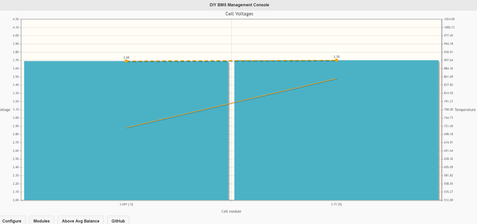
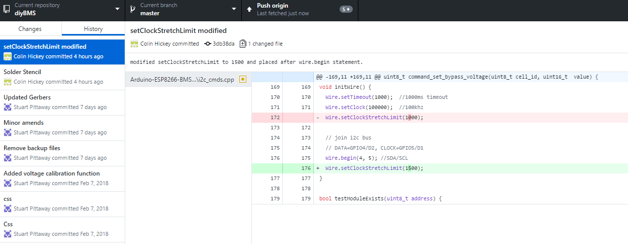
Hi Stuart, thanks for the instructions. That was the way i was doing it, i’d also tried with various pullup resistors but non seemed to work. I was testing with a nodemcu 0.9 board so i switched to a Wemos D1 board as it has built in pullups and received the same, i was looking through your code and after modifying the line Wire.setClockStretchLimit(1000); to be Wire.setClockStretchLimit(1500); but also move it to after the Wire.begin(4, 5); //SDA/SCL statement I was able to get some correct values and have two units hooked up as shown in my pic earlier. Really appreciate your help. I have a small youtube channel and wondered if you minded putting up a bit of content around your design and modifying it for grafana output also.
Great, nice to see it working Colin.
I’ve got two Node MCU1.0 ESP8266-12E units - the one works great and is what I’ve prototyped on so far, the other looks identical but as soon as I upload the sketch to it all I get is reboots and faults. A typical “blink” sketch works fine on both 
Happy for you to YouTube away on this device - although please include the warning that this is work in progress and may not do whats expected !
If you make changes to the code, please branch/submit these to github so I can include them in the master.
The node MCU i was using was very intermittent also, i had put it down to being the 0.9 earlier version. i just ran a test and it’s working fine with the modifications to the code without external pull ups on the nodemcu, i’m sure it has internal pullups but only found contradicting information when looking into it. I’ve submitted the changes to github so hopefully they should come through to you for approval.
Will mention it’s a work in progress and may change etc.
Hi Stuart, I had tried to submit the changes the other day but they didn’t show in the history for some reason so I’ve re-done them. Regarding any changes such as the grafana integration etc, would you prefer i just submit any changes to your master or would you prefer i fork the code?
If you are keeping the grafana stuff in a seperate module/class then happy to include - otherwise fork the code.
Here are the links to the capacitors I used (from Aliexpress) along with some other components which are good value
Assorted SMD Capacitors (1206 size)
https://www.aliexpress.com/item/Free-shipping-1206-SMD-Capacitor-assorted-kit-16values-20pcs-320pcs-0-5pF-22uF-Samples-kit/32359663409.html?spm=a2g0s.9042311.0.0.ujuHAe
Can someone please check If I have selected compatible components. Is it okay for some of the resistor tolerance to be 5%?
Here is a link to pdf of my cart:
https://drive.google.com/file/d/15FyF9Y7T-VUwflR5zofy1bo5wLETtnNb/view?usp=sharing
The ADUM1250ARZ, VISHAY SE30AFG-M3/6A, and the LED I will purchase from a different site.
Thanks.
I’m planning on putting it into a separate module but using the config page for enabling and config like ip etc but i’ll fork it for now as github is new to me and my coding a little rusty compared to yours, finished my computing degree 17 years ago
Finished mine 21 years ago ![]()
I wish I could buy components in the UK for those prices!
I’d go with 1% tolerance if you can get them.
Looks like you’ve actually been using yours though, I went into network infrastructure. BTW did you test that small change of the setClockStretchLimit increase and moving it to below the wire.begin declaration?
Colin I’ve not got any pull requests in GITHUB for the change. It is strange that you needed to change those, I’m using 2.2K pull up (to 3.3v) resistors near the ESP8266 on both the clock and data lines and its working fine!
I did a commit to your repository so shall look into a pull. Working collaboratively in github is something new to me and only worked on my own projects so shall go off and do some research. It’s strange as i I tried with various pull up resistors but it refused to work however with those two changes it works great. I think Adam is close to getting his boards soldered up so shall see how he gets on.
Great. Next topic then is how and when to do the cell balancing.
At the moment there is an experimental function “Above Average Balance” button on the web interface. This performs this action:
- Reads voltage of all cells
- Takes average voltage of all cells
- For cells OVER average, switch on dump load and request cell to drop to average reading
Obviously, this will still leave some cells out of balance with each other - but what other mechanisms and formulas do we need to investigate ?
PS: Additionally, we also need a good way to calculate the load drop on each battery when the load resistor is on so we can calculate the voltage in a more consistant manner!
I’ve been working on my own BMS design and have come across the same questions.
Right now I am turning on the dump load for all cells above average for 10 seconds, then I turn them all off to do another voltage measurement and repeat.
I also thought I could continue charging whilst balancing, but it turns out that as you approach 100% SOC, balancing and charging causes the unloaded cells to go overvoltage.