Well hopefully it’s not just me being stupid but i can’t see what else it can be as there is very little needed to get them going and changed the capacitors etc. I got some from Farnell at the mighty cost of £1.60 each !! I’ve sold my charge controller from electrodacus though so i need to get something going for the monitoring and balancing.
Well i have no idea why i managed to burn the track but for the minimum number of components you need C2 for it to function. It’s on the REG710 data sheet as well but i missed it, i was speaking with Adam who noticed my error. I have that much working so shall finish up a board today.
Looks like I’m famous!
Youtube video on the circuit and DIYBMS by Adam Welch

Adam mentioned he was going to be putting something up, he’s a good guy. I was going to ask you if it was ok to show the board on my wee channel, that is until i kept falling at the first hurdle lol
He told me he’d been speaking with you about it - my ESP8266 chip decided to die last night (keeps rebooting) so thats screwed me over until I can get a new one.
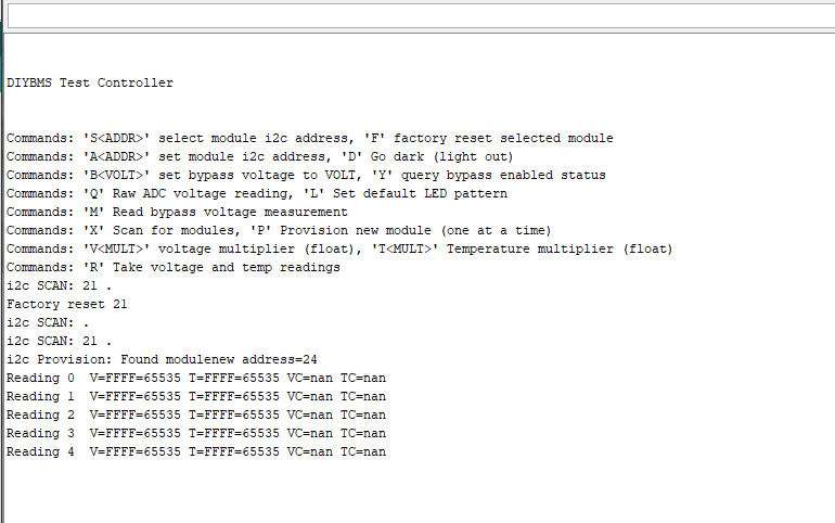
After provision, type S24 to select the module.
However, try using the other esp code, that will also provision for you
Hi all,
I am new to this and would like to know what files I need to send to have some boards printed, please.
I watched Adam Welch YouTube video and this circuit is spot on and I would like to build some units to support a 6s setup.
So I am new to GitHub and this community and would like to get up to speed…
Cheers
Hi @Stephen2 the Gerber files for making a PCB are here
https://github.com/stuartpittaway/diyBMS/tree/master/BMS-Cell-Module-Circuit/Gerber
we used ALLPCB.COM which I think now charge about 15 USD for 10 boards.
Note that the code doesn’t actually balance the cells at the moment - its still work in progress (although the basic function is there).
Hi,
ALLPCB look to require some info before they quote.
the size of the board, does anyone know what the dims are in mm.
Also do we order 2 layer, what have people purchased.
And what pcb thickness have people purchased.
Cheers,
Its approx 55x55mm the actual measurements are calculated when you upload the files in the next step.
Just accept all the defaults - 2 layer and standard thickness
Thanks Stuart i tried with the other ESP code as well but it just wasn’t wanting to provision, i’m debugging now to check things. BTW I’ve created a printable solder mask for the boards if your interested
Great idea - I’ve a 3d printer sitting idle!
Just ordered 10 boards from jlpcb. It came out to $11.03 shipped. Thanks for sharing the design. Im not really sure what Im doing due to my very limited experience (highschool student) but i think it will be a fun project.
I too have just ordered 10 boards from jlcpcb boards costs $2 plus postage at $9.03.
Which after the exchange rate conversion comes to £8.14
I take it your in the UK Stephen? are you sorted for all other components? I ordered the majority of mine from aliexpress.
[Hint: Click on the green ‘S’ and you’ll see his country. Moderator - RW]
Hi Stuart, i’m really close to getting things working and i did have a fleeting moment where i got a correct reading before it disappeared. To go back to basics how are you connecting your modules to your ESP8266?
I’m connecting 4 wires (+3.3v / 0v / i2c clock / i2c data) from the ESP module over to the 4 way connector on the first module, this then daisy-chained to the other modules.
Just start with a single module for now, when you provision them you must do it one at a time otherwise you will get i2c address conflicts.
Looking at the code, its using ESP pins DATA=GPIO4 (D2) and CLOCK=GPIO5 (D1) although I’m not at home to double check.
Yeah that’s how i’ve got it connected, did you need to do any manual pullup resistors or similar?
When i’m provisioning i’m doing them one at a time but they both seem to get assigned 24.
Yes you will need a resistor for pull up on the ESP side - think its 4.7K.
If you factory reset the module and follow this process:
- Connect ESP and 1 module
- Click the provision button and allow module to restart
- Attach 2nd module to 1st module
- Click the provison button and allow module to restart
Repeat for each module and they should all be provisioned with different ID’s. You may need to reboot the ESP module when you are done which will then scan the i2c bus looking for module ids.
Sorry I’ve not been updating the code, have some home renovation work going on and that’s taking time away from this project!