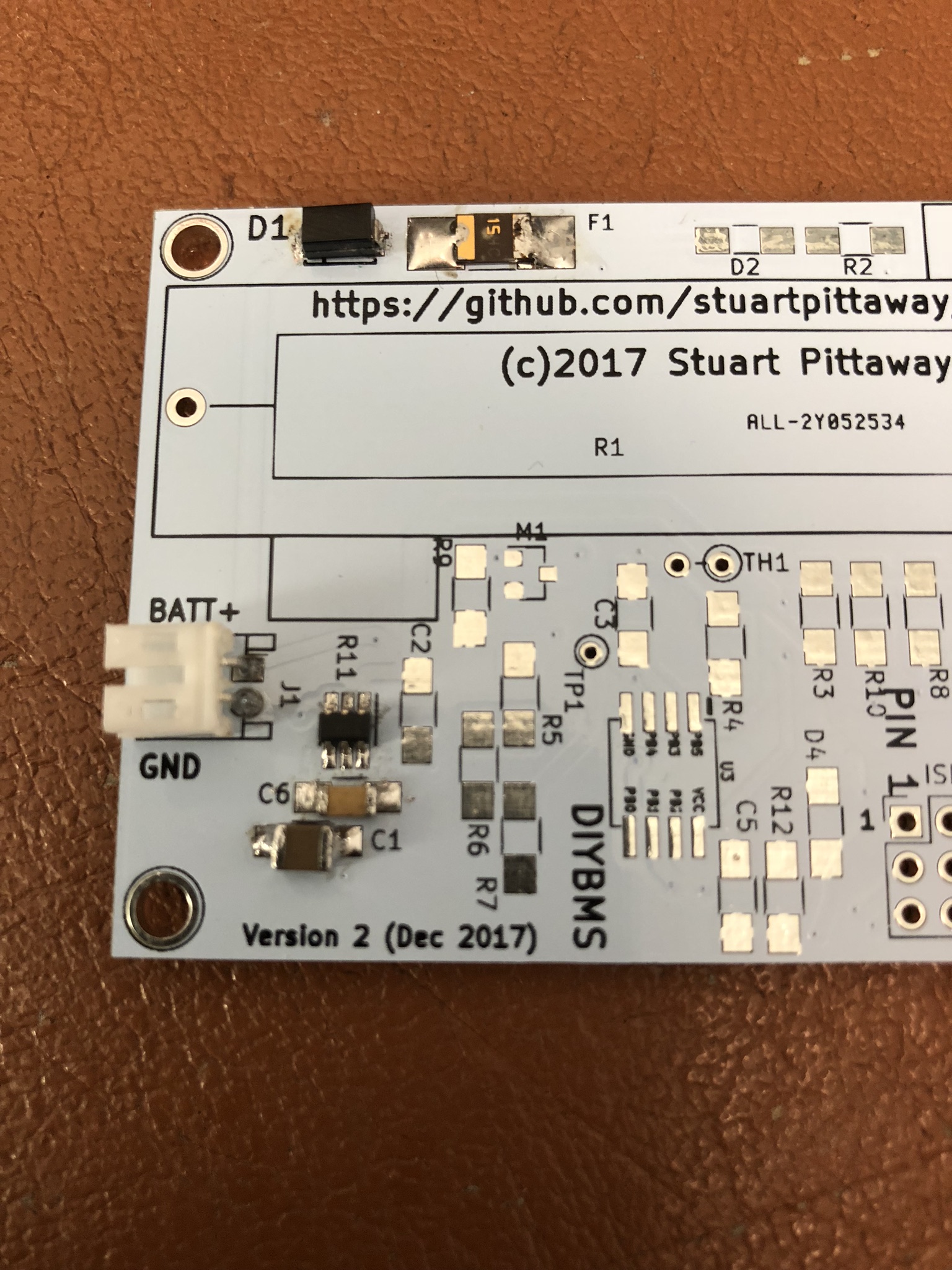
Yes, the REG710 is the “proper way up” - same as the ATTINY, pin 1 top left nearest R11/C2.
That device is tiny and really difficult to solder to, even with paste I got small bridges between the pins & I really need to scrub the flux off my solder boards!
Note that I’ve also left the thermistor high over the board, my idea for this was as a monitor to the heat from the load resistor - so once the resistor is in place, I folder the thermistor onto the top of it.
Those 2 pin JST connectors are a real pain to wire into as well !
Thanks Stuart, i was just writing a message about how i was still struggling and i’ve had the 3.3v regulator off the board and back then off again and took the pad off in the end and still no ball so went back to basics and checked everything again and i’d put the diode the wrong way around, feel rather stupid but a lesson learned! i have another 13 so shall chalk this up to a practice one! The solder paste arrived today so going to try the heat gun method this time.
It couldn’t last long really as the shipping alone must have been killing them. https://jlcpcb.com/ have an offer on at the moment for $2 for 10 pcs i think.
I got 14 boards and have a 7s pack so i should be good but really appreciate the offer. i’ll hopefully get a few boards done when the kids are in bed at some point so i can get them hooked up.
Yeah thanks got plenty of them knocking about in various forms. Just been doing some more tinkering tonight and seem to be getting 1.7v out of the REG710. I’ve verified that there is continuity from the output of the fuse to vin (pin 5) as well as enable (pin 3) also verified connections to the pump capacitor connections, all seem good but i just seem to be getting that output.
Yeah was curious on that myself, but just checked on the multimeter and they checked out ok. I’m sure i’ve done something stupid so will have to look over it again.
Thanks for taking the time to respond, I did wonder if i had the right versions as well but did the same and looked at the datasheet and saw the same thing that none go that low. I’m using ceramic capacitors so there shouldn’t be a polarity issue. I did try another board and just setup the diode/fuse/REG710 and the charge pump capacitors but it went from bad to worse and it overheated and burnt a track out on the rear of the board where the diode was. I gave up on it yesterday so shall have to take a fresh look at it tonight if i get time.
Don’t bother with the fuse/diode - just solder in a wire link to bypass.
The REG710 chips are tiny but they should be hand solderable. I’m using SS34 diodes by the way - the diode doesn’t really matter, just for reverse polarity protection, but it will need to carry the whole bypass current (SS34 = 3Amp)
this board doesn’t like me lol, i put just REG710 and C6 on with a bypass on the fuse/diode. I was getting 4v on the output at that point which doesn’t make much sense as it doesn’t match any of the chip specs. I then soldered on C6 and was measuring and got the lovely magic smoke smell, burnt the board in the same place. Scratching my head a little.
I’ve just been using a single 18650 charged to 3.7v. I’ll try with a current limited power supply as i do have one. It’ll be something I’ve done i’m sure, i got the boards from the same fab house and using the same design so be surprised if it’s the boards, really appreciate the offer though. It’s funny the first one didn’t do this.
I’ve started again with a fresh board and components. I’m now getting a solid 3.8v which is something although not right lol, i’ve measured the capacitors and they are fine. I’m using a regulated supply which i’ve set at 200ma and tried from 3.2 to 4.1v and it always outputs 3.8v. I think i might have to order some more REG710NA power regulators, there is a guy on ebay who has 5 for £5 so i might get a set those just to test with.
Re the shorting of the boards I can only guess i’ve done something totally stupid, i had tried re-using the REG710 i’m sure so maybe i screwed it and that has led to the short, i got myself confused by removing and re soldering things when troubleshooting.
Yeah i think that is going to be most likely as there doesn’t seem to be any shorts and the capacitors checked out. Where did you get your REG710 chips out of curiosity, mine were aliexpress which would tie in with the cheap Chinese clone theory