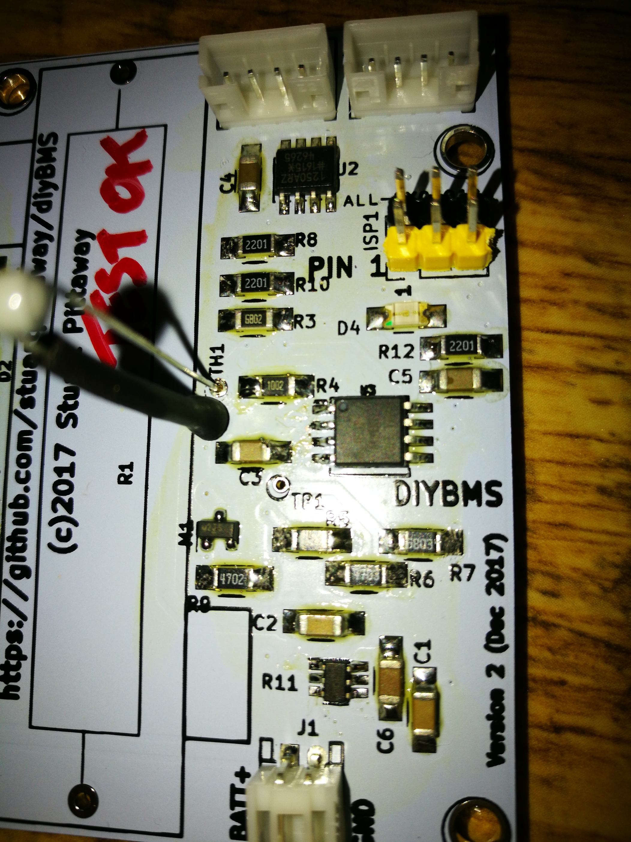
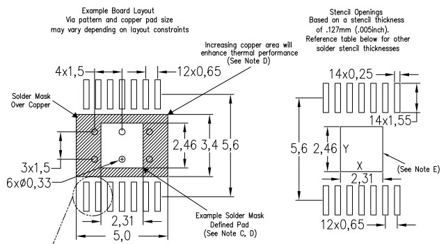
I used the TPS55340 in a 14 pin HTSSOP package with 0.65mm lead spacing on my BMS PCB. This thing has a thermal solder pad on the underside so is not easy to hand solder.
My solution was to purchase a cheap hot air re-work station off ebay. This works like a dream. You even see the little jiggle that occurs when components self-align as they go through the re-flow oven. Brilliant.
I’m with you there, i guess it’s just because all the stuff i work with is 2.54mm pitch so have lots of those lying around already. I priced the parts up for aliexpress vs farnell and it was a good £10 cheaper for everything but i’ve gotten 300 of each resistor/capacitor rather than 20 from farnell.
This is the model but I forget which seller I used.
The price is crazy cheap but the hot air and the soldering iron both work very well.
I recommend you practice on some scrap before trying for real. The common mistakes are too much air and/or too much heat.
Too much air and the components become airborne. When you find the optimum settings start about 150mm from the target and move in slowly. This allows the PCB to get up to temperature without roasting the components.
Flux is very important. I use a no-clean low viscosity product from CPC.
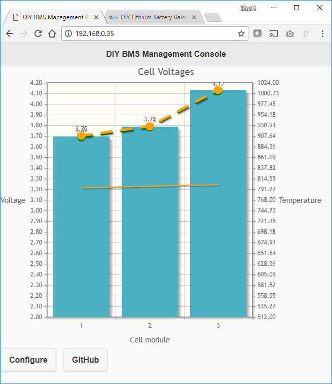
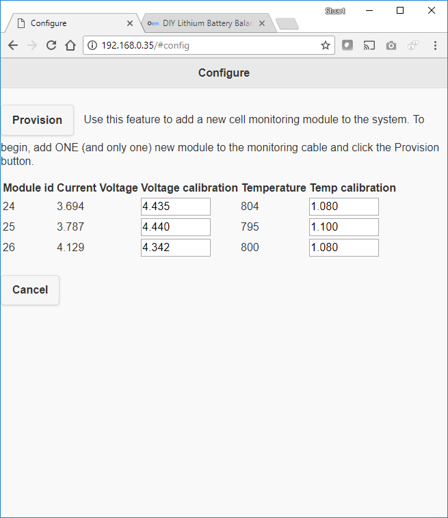
I’m seeing 4mV resolution - the calibration values are used to multiply the ADC output
I’m oversampling and averaging on the ATTINY chip, take a reading every 1/4 second and average over 16 samples.
Both the above screenshots are part of the ESP program and additional scripts hosted on GITHUB, they update every 5 seconds with new data from the sensors.
On-chip 2.56V reference on the ATTINY85 chip (running @ 3.3V) - its fairly accurate
I’m also pushing the voltage and temperature values over WIFI to emonCMS which can then be used to provide other graphs etc.
Going to have a go at writing the cell balancing code tonight!
OK, I also have 4mV resolution (10 bit ADC on the Mega 328).
I also used an oversampling technique but the repeatability was not good. I consistently measured deviation of 10 to 20 mV.
After posting a request on the arduino forum I received some excellent advice from Tony Wilk who wrote a short exponential filter for me. This improved things significantly.
Thanks for that I’ll take a look at the code. I also get some bounce in the readings, however it won’t really affect anything, you are never going to get 100% accurate balancing with the type of circuit I’m looking at - and most cell manufacturers specify 0.1V maximum out-of-balance so not a problem really.
Agreed, in your case with only one cell it’s less of a problem. With eight series connected cells I have a cumulative error which can add or subtract the error of each cell.
The only published data I have seen regarding constant current cut off voltage is 4.2V +/- 50 mV
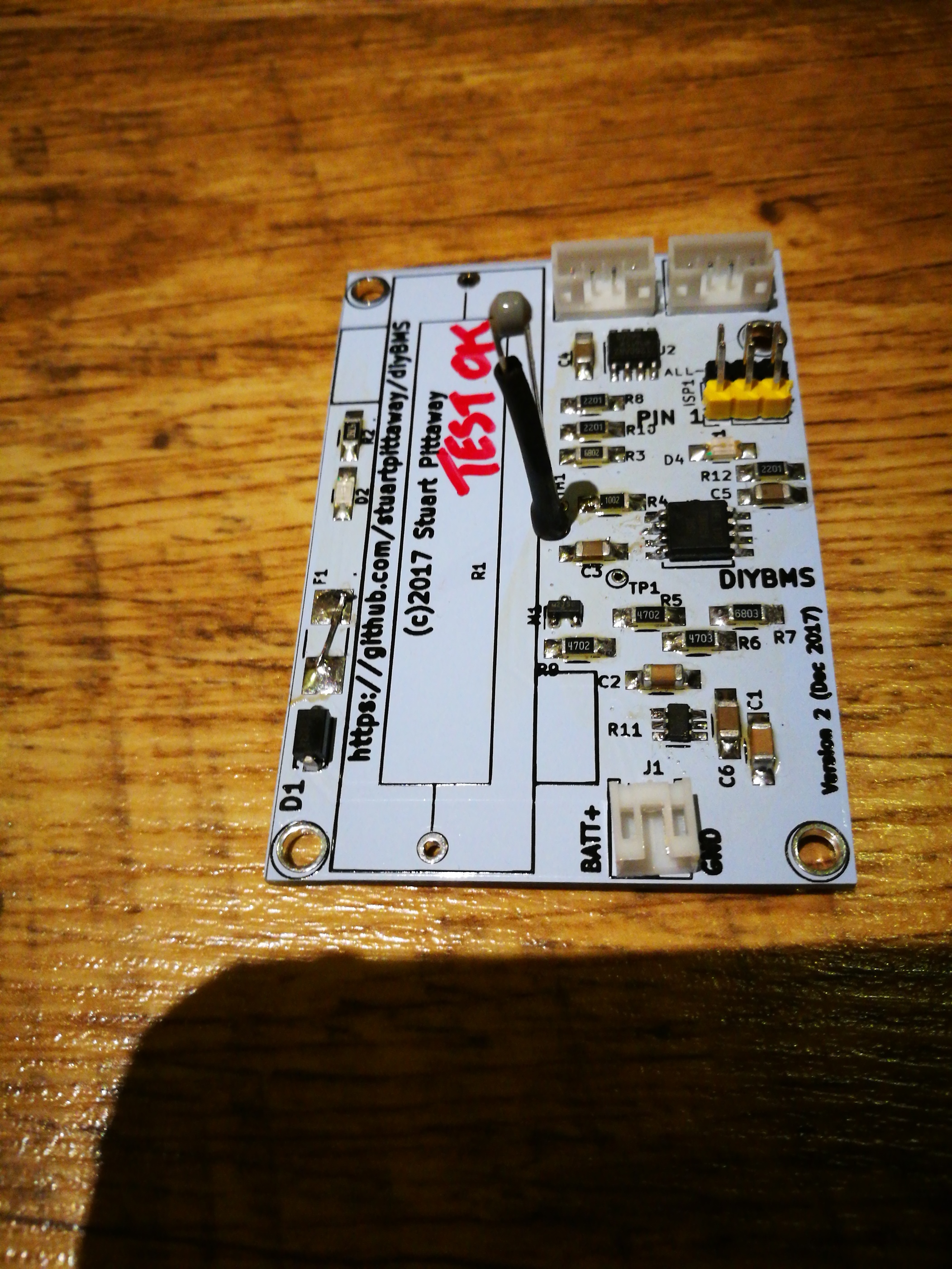
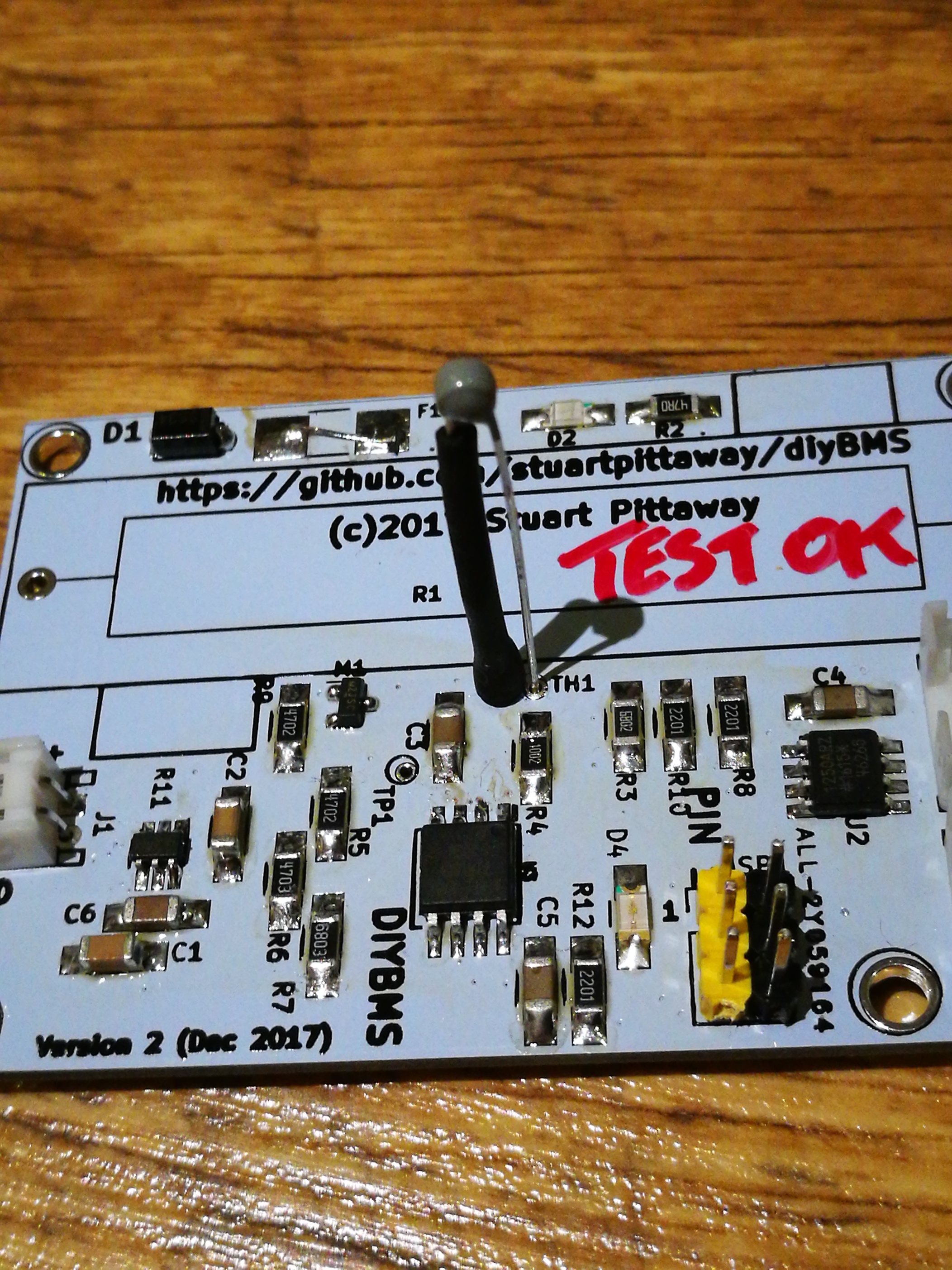
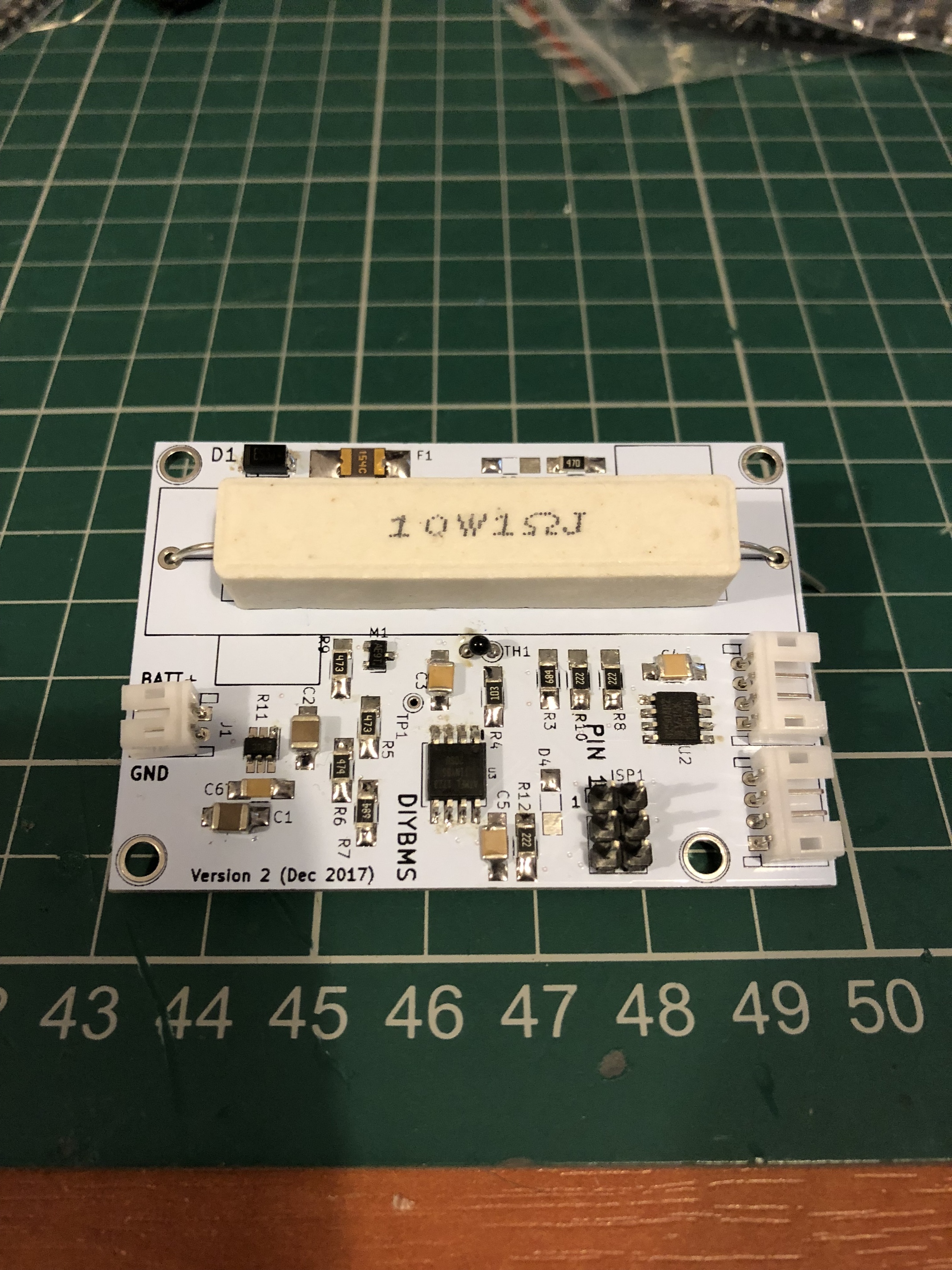
Have soldered one up, just missing the leds. Need to get some more ceramic resistors, just placed it there for the pic. Soldier paste isn’t here yet so did it by hand just to get going.
I’ve built another 4 modules today, took about 2 hours all manually soldered using paste and a hot frying pan!!
2 of the 4 didn’t work, so I unsoldered the CPUs (destroyed them in the process) only to find a wire in my Arduino programmer had broke off so the boards were fine.
Reminder to myself to check the obvious things first
Bummer on the cpu’s, hard to desolder in one piece though. Do you have any images of your soldered boards? I’ve only gotten one done as i was waiting for the solder paste to arrive rather than do any more by hand with the soldering iron and not having much luck so far. I’m wondering if i’ve read the circuit diagram correctly for the placement of the component orientation.
 so the boards were fine.