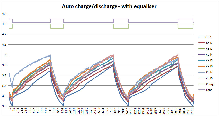
The graph shows 8 series connected cells discharging at about 0.4C. The tick interval is 10 Seconds
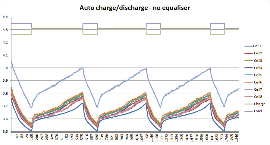
You guys have more experience using these cells than I do. What level of imbalance should I expect to see? Do you have any empirical data?
No I dont. You could try charging a single cell to full and let the equaliser do its thing?
Good idea. I shall try that.
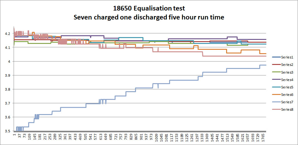
You will notice that the discharged cell (No 7) is mostly affecting the cells immediately above and below No 7. The impact on cells further from cell 7 is less which is what you would expect.
So, it is clearly working which is pleasing.
Mine arrived and they sent me 20 boards ![]()
I am looking forward to seeing some data from you guys!
Meantime I started a thread on the DIY Powerwall site you may find interesting:
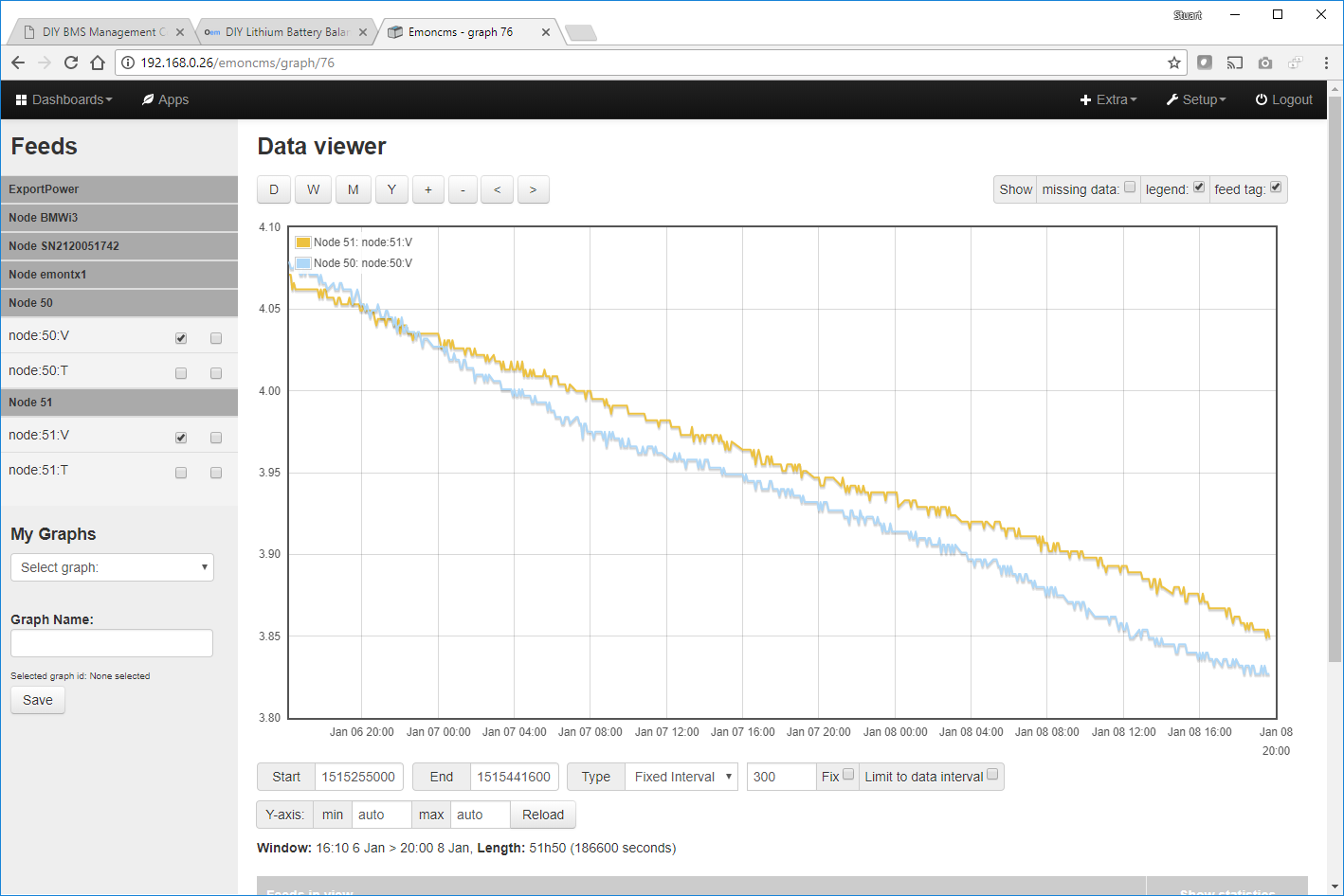
I’ve updated the controller code to upload its voltage and temperature readings for each cell to emonCMS (over network).
Code is over here
I’m going to spend a few hours tonight putting together some of my new PCB circuits and setting up a test rig with some 18650 cells.
I signed up for an EmonCMS account but never actually used it. I currently use grafana which looks great although being time based does have issues at times showing eroneous figures.
I’ve made the code fairly modular in this respect so it can support other data/graphing engines.
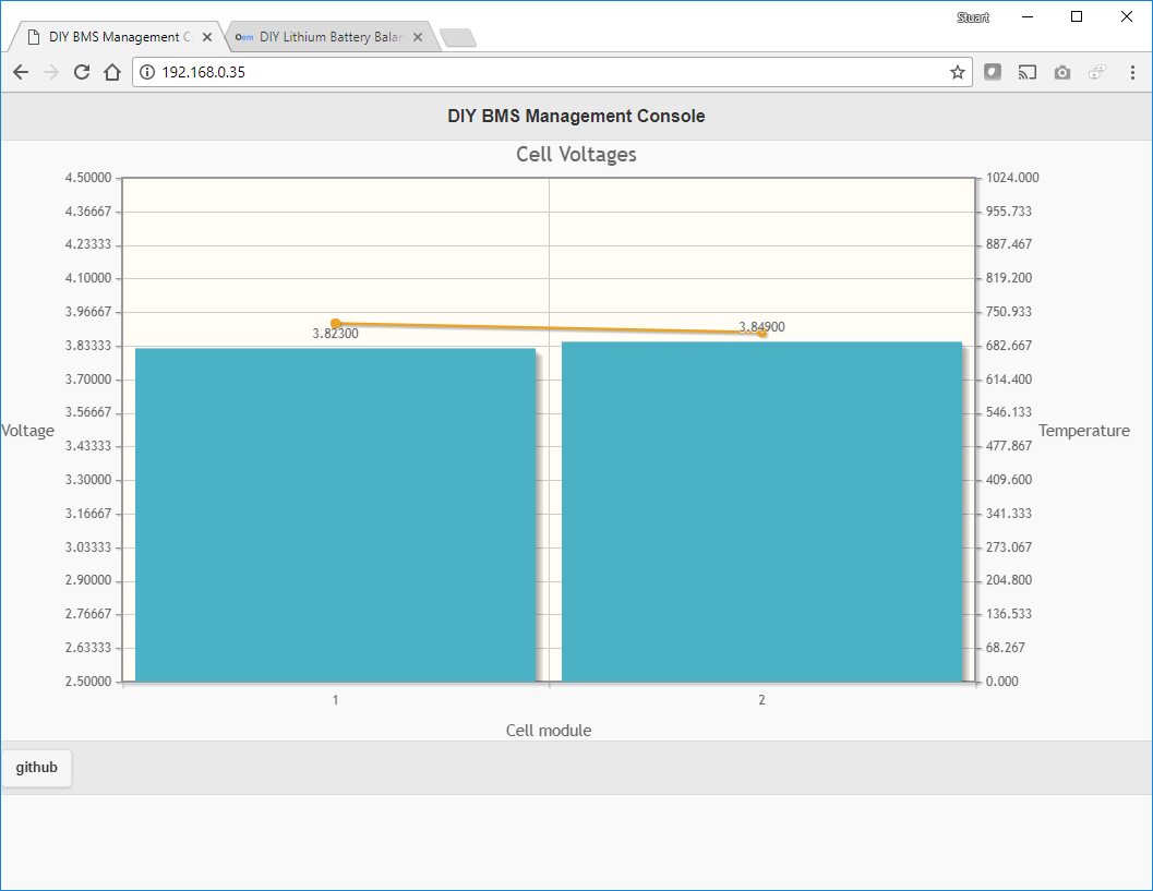
I’ve also started on an inbuilt dash board to view the cell voltages and provide some control on the modules. Times slipped past me this week though!
Brilliant, i’ll merge my grafana code in for ease of continuity and then i can look at EMonCMS in the meantime as it may be better. I’m just back from a business trip but should have a free day on Sunday to have a look, although i do have a new Prusa MK3 sat in the corner waiting to be built as well.
Christmas has come early then! I’ve a MK2 clone which works well after a bit of tweaking. The MK3 looks great though.
Progress update:
- I’ve built 4 circuit boards all working

- I recommend changing the resistor value on R3 to 68K instead of 20K to give the thermistor a better range
- The ESP code can upload voltage and temperature readings into emoncms
- The ESP code has a web interface for monitoring cell voltages and temperature
The code doesn’t actually balance at the moment, but the ATTINY does have the function written, just not completed yet.
Looking good and i see you’ve been making some modifications. I’m still waiting on a few parts as i took the aliexpress cheap option and i lost my ADUM chips but finally found them last night! I have some 603 sized caps/resistors which may just fit so could try doing a board with those in the interim.
There’s lots of space on the board for the resistors and caps so should fit okay. I tried using solder paste for the first time last night on the caps and resistors - worked really well (I heated the board in a frying pan!!)
haha love the frying pan idea, I’ve seen a lot of people making diy home reflow ovens but seems a lot of work for the amount of boards i make up currently. The 603 sized components are smaller so will definitely fit it’s just a case of if they shall span the gaps sufficiently. I’m really keen to get this up and running and i think i’m going to sell the BMS/Charge controller i got from electrodacus as it won’t work as well for my needs.
I was surprised how well the frying pan worked - no idea what the temperature was so I’m not going to use it for the chips.
Soldering the FET on it a pain - its tiny and the regulator pins are so close together as well !
I might get some solder paste and try as i’ve not done that method. Oh i meant to ask was there a reason for the connectors using 2mm pitch rather than 2.54mm as that caught me out as well, i know it’s in your BOM but i just presumed it’d be 2.54mm.
Col