Hey, this is my first post in this community and i’ve just finished my 7s-Diy-Balancer for testing purposes (V3.0 September 2018). So far, the cell moduls seem to work fine:
But I dont understand the balancing function entirely: By pressing the “Above Avg Balance” button, the cells with (relatively) higher voltage dumping their current into the resistor R2. This process takes less than a minute. But how can I enable a permanent auto-balancing in the BMS controller?
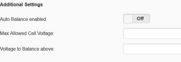
The additional setting in the configure-menu has no effect to the balancing…
I already tried to enable the Auto-balance with “max. allowed cell voltage” of 4,14V and a “voltage to balance about” at 4,1V and hit the Save-button. Is this the right way to enable the auto-balancing? I carged and discharged 7 18650 batteries, but no balancing occurs (like in my first uploaded screenshot).
Could someone explain the auto-balancing function to me?
And thank you all for contributing to this project!
Hi Klaus the way it should work is that the max allowed voltage is just that in that if a cell goes above that voltage it will enable the bypass and attempt to reduce their voltage or at least keep it from rising by dumping into the power resistor. This is totally independent of the auto balancing.
The settings required for auto balancing are to enable auto balance and the voltage to balance above. In my setup i typically set this at 4v. What this means is that it will only attempt to balance above this voltage. This was implemented as if it’s set lower and you have a imbalanced pack it can continually try to balance the pack perfectly but in the process dumping a lot of energy.
In you screenshot if you wish to kick it into life then you can set the voltage to balance above to say 3.6v and enable auto balancing and it shall then try to balance the pack. Be warned though if you have a large pack it could take some time as your 5th pack is quite high compared to the rest.
Hi Colin, thanks for the quick reply!
Ok, I think in theory I understand the function now I’ve tried it in the way you explained to me, but nothing happends. No LED is flashing and the resistors doesn’t heat up (especially the 5th one should…). The values i’ve entered into the settings form also disappear, when I visit the setting-menu again (maybe they cant’t be saved to the ESP8266?). But the popup in the end of the form show up “ok”, by hitting the save-button…
Hehe, ok. It seems that I can’t save the changes to the ESP8266. I hook up the system to my computer and hoped for some error messages in the serial console. But there is no indicator for a failure. Do you know which funcion / class in the BMS-controller code is responsible for saving/loading the data to the ESP? So i can have a look to it tomorrow? Thanks!
Hello All
Just finished provisioning my 7th board only 7 more to go.
I am still not sure what the thermistor is doing in the overall system.
Ie Is it measuring R1 or the Batteries ?
If it measuring R1 and the temp get to high what actually happening, i dont want it to stop discharging if the cell is to high. Can someone please share some light on what is happen if this is the case.
Now if its to measure battery temp, is it not a bit short and does it actually fit in between the cells. I am wondering why couldnt with add a header type configuration and then cable the thermistor to were ever it is needed. (Similar to what we do when measuring temperature on a 3d printer heads). I also wondering why we couldn’t add more then 1.
Sorry i may not be understanding what is happening, happy to be educated.
Thanks
Andy
Hello Andy, the thermistor was originally designed to monitor the temperature of the load resistor R1 - it should be in the correct place to bend under/over the R1 part.
The R1 resistor can get VERY hot - 100+ degrees C so there is a risk of burning to you and objects around it.
So the original design was to then limit the discharge until the temperature was cooler. I say originally, as the code for this was modified by others along the development so at the moment, the thermistor does nothing but report the temperature of what ever it is near.
If you want to make a header/remote sensor then you can - but note that the thermistor must be connected for the module to work.
Hello My name is Sven and im new in this Project.
I Order the Pcs from Elecrow and received it fine.
For the Controller i use an Esp12E.
Both firmware seems working but i can not Provision the module.
The i2c Stream looks fine (Start 24 write 10 stop, Start 24 read 12 ack 175 stop…)
But in the Webconfig everytime “There is no data available, please configure modules.”
Have anyone any idea what else i can Try to find the fault?
Greeting from Germany
Hi there , are the batteries in your setup directly connected to the UPS ? If so wouldn’t it keep float charging them like a lead acid ? I would love to do the same but need to have a solution to disconnect the batteries when charged and re-connect them if there is a power outage.
Start with a single module connected to the controller. Do you have the i2c resistors connected to the controller ESP? Have you mistakenly swapped TX/RX connections?
Hello
I Have connected a single module. Two 4,7k resistors to Vcc. The signal looks Fine. I Think The 8266 read the signal but not show it.
I Listen with an Logic analyzer and see the Data from 8266 to the Module and Back from the Module.
(Start 24 write 10 stop, Start 24 read 12 ack 175 stop…) Witch ist in the Specs 10 for read_voltage from 8266 and answer 12,175 (12*255=3060)+175 = 3.235v Witch ist exact what i put in.
I Reflash the 8266 with new Firmware and i2c Data Stop. When i Click Provision the Signal ist Back but The Website still show no module.
I not know where to find the Problem Perhaps i Build an master module myself.
Have you set the fuses correctly on the ATTiny85 when you put the code onto it? Also are you using pullup resistors on the ESP ic2 lines?
I had a similar issues and was tinking with the code for some time and managed to get it work by changing set clock strech which sort of worked but was really just masking the fact i had not set the fuses correctly for chip speed etc
Is Programming the Module (tiny85) with Provision only possible one time?
I stop trying with the esp8266. I connect the Module to an Arduino with Lan (w5500) and send the Voltage via Mqtt. Reading Voltage ist ready but Set config ist missing.
Perhaps i can Post the Code here next days.


 Perhaps i Build an master module myself.