Thanks for your answer. First I will just monitor stuff. If this works I will build a addon pcb etc and make the changes in the code. Once I am on it will will report back.
In the meantime I created a 3D print stencil for the v3 (latest version with only resisitor R6 for the voltage dividor).
I’m new here, and have today read through the thread from start to finish. I have just ordered 20 boards and need to get all the components to solder on. Is there a complete parts list, the one in the github, is very generic e.g. 47K Resistor, what size, SMD right?
Just trying to make sure i order all the right stuff.
Its very difficult to give parts lists as suppliers keep changing catalogues and discontinuing products!
However, most parts on the smaller PCB are all 0805 size. I’d recommend downloading KiCAD and then looking at the components - you can see the foot print will read something like “Capacitor_SMD:C_0805_2012Metric_Pad1.33x1.40mm_HandSolder” - which is an SMD 0805 capacitor.
OK, I have downloaded the KiCAD software and opened the pcb file, and if i zoom on the footprint i see something like Net-(C3-Pad1)
I am not sure what that means, I can see from the label on the side it is 0.1uF, meaning it’s a capacitor, but not seeing the description like you mentioned which specifies package size.
I think that is possible to do more math with this BMS,
the time of balance resistor is ON is correlated with charge removed from single power-wall element, and this charge is a good indicator of capacity displacement between elements,
so i suppose that with some data mining BMS software can suggest how many mAh you should add to weak element to avoid(or reduce) balance.
I suggest to give (with webapi?) the total ON time of resistor in a last day/hour range.
I did as Stuart suggested and pressed E to show the footprint and think i got everything right. I compared it against BMS_Cell_Module_BOM.html in the github, but there was some differences.
Anyway this is what i ordered:
0805 SMD Resistors 10K, 20K, 4.7K
0805 SMD Capacitors 100nF, 2.2uF, 220nF
0805 SMD LED’s Blue and Green
Schottkey 40V/3A SS34
Reg710NA-3.3
Adum1250ARZ
ATTiny85V-10SU
10K Thermistor B57891M0103K000 NTC
SI2312BDS-T1-GE3 Mosfet (Hopefully this it the right one, couldn’t find E3, got GE3 instead.
The 4 pin and 2-pin connectors
and the pin headers.
I haven’t yet ordered the power resistors, what rating do i need?
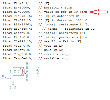
What resistor is this on the v2, v2.1 boards,
is it R3, or R4 ?
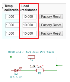
Also what is the “Load Resistance”, is this the ‘dump load’ ? (R1 on the v2, v2.1 boards)
One final thing, when I was playing with my setup on my bench, I had things working fine,
but the next day, the web front end would not show any graphs
and when I looked at the ‘Modules’, it said I had to redo them ( couldn’t find any )
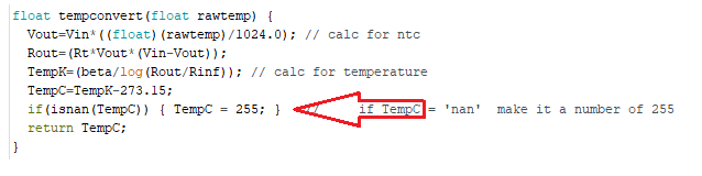
so I fired up the console to see what was going on, and as it started, it showed the temperature value as ‘nan’ ( not a number )
so I hunted through the code, and added this,
Hi Stuart and Colin! My first 5 modul works like a charm thanks to you guys. Every board is hand soldered. I have never soldered smd, especially not 0805 sized parts, but it went good and I had finished it in a couple of hours (with a few mistake ).
However I have questions:
Does it matter if C5 is not polarized? (I used non-polarized capacitors)
One of my REG710 regulate to 3.2V only. This board is quite inaccurate, the voltage level is drifting a little. Can it be caused by the REG710?
After I set the temperature manually the ESP reads 0 V and I have to factory reset the modul to make it work again.
What is the easiest/fastest way to factory reset a module if one went missing? Currently I erase EEProm through ICSP via Arduino UNO.
What can I measure on TP1 VDIV pad?
At first I will modify my good old 800VA UPS and test the boards (4S). Then I will move to the “big” boy, a 6KVA UPS with 7kWh battery
Okay. Last night every board went into panic mode. The ESP don’t see any of it, i checked out on serial monitor, so my guess is its a communication failure or the ESP somehow resetted itself. As I mentioned before i can not calibrate the temperature therefore it reads funny values. If the temperature rises the value rises too and after a certain point the high value of temperature kills the webservice (make every board disapear from main page and from modules page too). If the temperature go back to normal then the modules are visible in the webservice again.
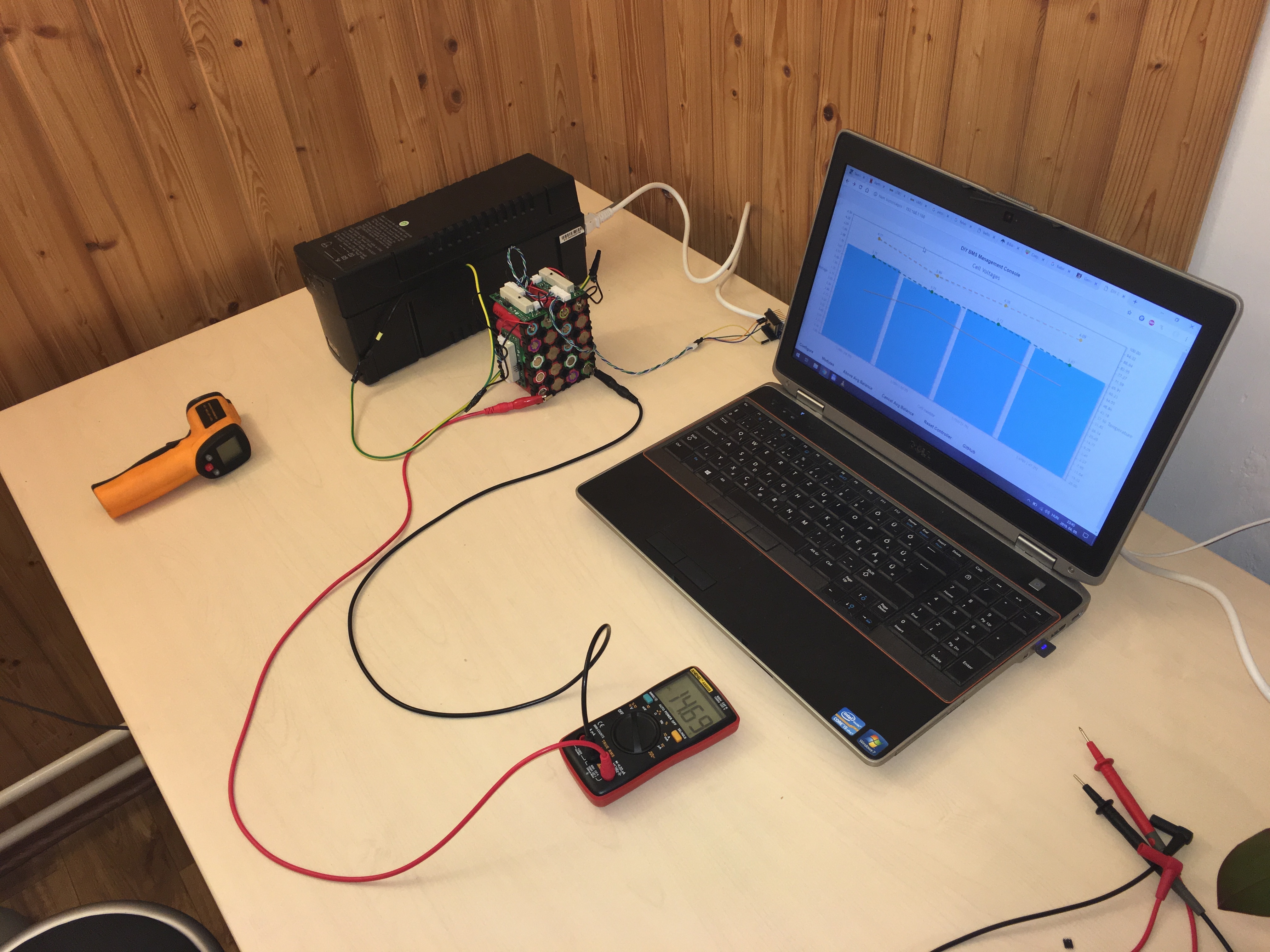
So last night I put some battery together (4S5P) and put the pack into a 800VA UPS. I dischareged the whole pack, cells went out of ballance as I expected. I set auto balance voltage and max voltage and I let them charge up the whole night. And here I am. With my DMM I can confirm the auto balance did its job, because the pack is well balanced.
Some technikal details:
R4 is 10K
R1 is 10W 2 Ohm
Pack voltage is 14.50V
Voltage to Balance above: 3.62V (14.5/4 = 3.625)
Max Allowed Cell Voltage: 4.10V
Latest firmware on modules and esp too
Do you guys have any advice for me where to start looking?
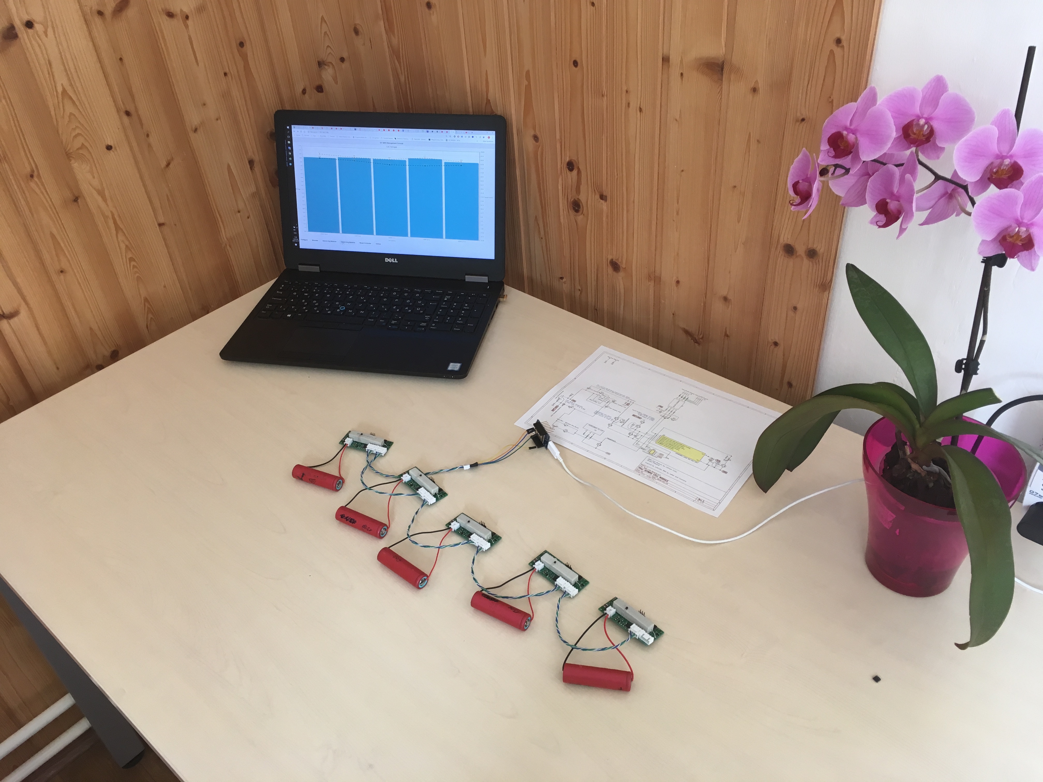
Okay, I find out that one of my board is faulty. Seems okay, but if I add it to the daisy chain it do some funny thing with the i2c communication. Now I am able to calibrate the temperature. At least I have 5 and only need 4 of them right now. I will inspect the faulty board at the weekend and keep testing the other 4 board. Here is my test setup:
The battery pack is very uneven on purpose so the boards have a lot of work to do to keep them in shape. Also contains some heater sanyo to heatstress the boards. Every cell connects to each other through fuse wire in case something goes wrong.
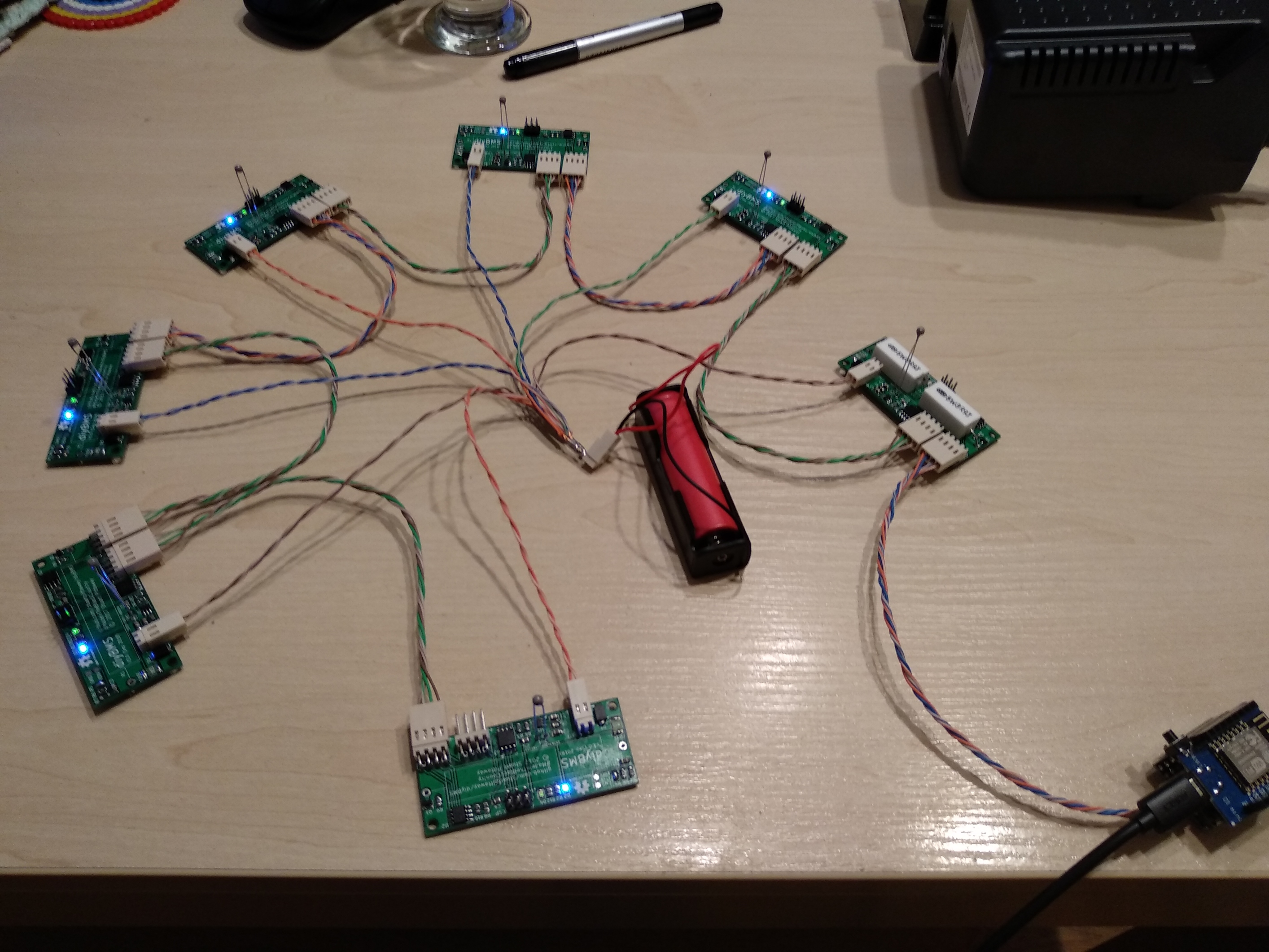
Hi! I’ve been watching this forum and few other sources for a while. Just finished testing my 7 boards and all seems fine. It was my first SMD soldering so I was really worried. Now I have to speed up 18650 testing to get those some real job to do. I’m really impressed by work everyone behind this project.
 ).
).