I don’t know if sven is having the same issue I had, where I provisioned my modules and they were working fine, the next day, there was no modules to be seen and it was like they had not been provisioned,
what I found in my debugging, was the temp value was returning was a “nan” (not a number) value, which appeared to break the code showing the modules,
so all I done was change some code, so when the temperature was read, and it returned a ‘nan’ value, I just insert a value of my choosing, this fixed my issue,
example of my code is above from ( April 1 )
Nigel
Thank you Very mutch. This was the Problem here too. Now its working fine.
Now im looking where the Nan comes from. I saw the Temp Data on i2c bus and in celljson there is an nan.
I also had problems with the module not appearing on the page, with the old version of the code, it appeared on the page but not with the new one, after looking at the modifications made, it was discovered that it was something with the temperature and after doing that modification it started working again . I do not know if it was a bug but it worked.
but the temperature is not working, the value does not change.
Hi , I am building the smaller PCB. Diode D1 in the BoM is SS34 which is DO-214AB package. However the footprint of the PCB seems to be DO-221AC. As a result my diode is too big to fit on the PCB. Would be thankful for any advice.
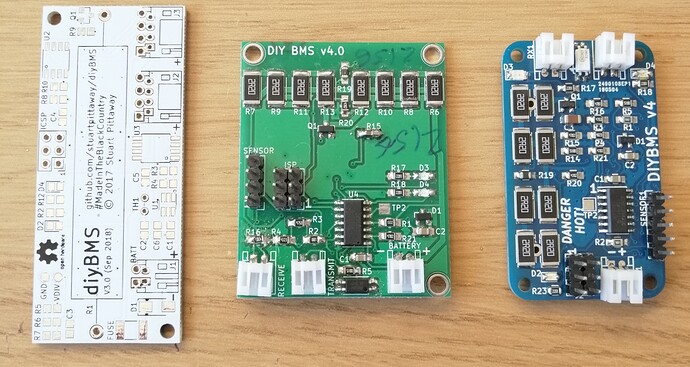
Here’s a preview of version 4.
On left, small v3 PCB, a version 4 prototype and hopefully v4 final.
Final is 30x50mm in size and uses ATTINY841 chip
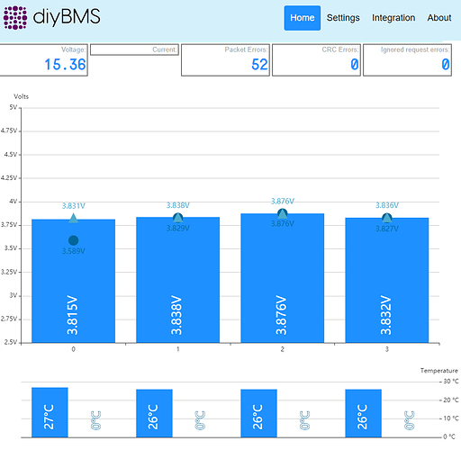
Screenshot of the web interface showing cell temperature, board temperature and voltages. Accuracy should be down to 2mV (0.002V)
Perhaps install it vertically with a small wire from the other pin to the end of the diode?
Or just miss the diode out completely with a jumper wire - its there to prevent reverse polarity (be careful!)
The 841 have more IO this is great. Perhaps its possible to update the PCB with one Output more. So it is Possible to use this for a Shut down Bus.
My Plan every Balancer module can set an signal when voltage is to high or to low. This Signal through an Diode to an big Mosfet between the main.
Hi Sven, in my opinion your better off doing a bypass at the whole pack level rather than at the module level. If you bypass one individual module your going to cause issues at all the other packs.
I agree, the ESP controller module will take care of the external input/output with a seperate relay module.
However, just for info, each v4 module has 2 spare I/O Pins available - these are broken out onto the “sensor” header - shown on the right of the PCB.
Yes ofcorse but every Module can turn This Bypass on. So we can turn it on when i2c go to Panic mode too
I solved my problem. I used a ESP8266 clone. Now I bought a original ESP8266 and I can save the configs  The balancing is working fine now - thanks!
Slightly different topic, looking at controlling external devices like chargers and inverters - what type of relays, optical interfaces or similar would you expect to see/use ?
I’m thinking that a controller board with a couple of digital I/O (opto isolated) and a couple of relays would be enough - thoughts?
What sort of voltage and current rating should the relays have?
Great idea! Been talking about a little bit with Colin. I would be interested in having 3 relays controlled which can be used to control contactors, they require a 12v circuit, not that many amps( i’ll measure that tomorrow), but preferably with values Read from influxdb/grafana (min&max cell voltages and alsof min&max overall voltage).
I am no coding-hero, but I really love all tour work and input from the community
Although i think i should better have waited for those beatutifull v4 boards 
Hi @Maarten_van_der_Voor
Glad you have interest in adding some relays. I don’t think I could drive these from Grafana data but the new controller can drive them easily enough, based on the values from the modules
We will probably need some relays with a decent current capacity (AC+DC) to provide multiple purposes.
Do you also measure current? There is a spare analogue input on the ESP that could be used to monitor DC current given the correct sensor.
Do you have any need for additional inputs from other sensors? Perhaps a “emergency stop” button !?!
yes a e-stop would be great(in a normally close circuit) for protection some other digital input (isolated) and some digital output (relay or digital) would be good but the analogue input would be great to monitor the energy movement (in and out of the pack) and overvcurrent protection of the pack
Whilst playing with the controller code and a Wemos “D1 mini Pro” - clone I found this problem the hard way…
3.3v regulator is now toast on the board, but if I power 3.3v rail from external power supply the chip powers up and works fine. Suspect I must have shorted the regulator out at some point and its not happy now!
Hi Stuart, thanks! That of the analoge input for measusring current would be nice too! Especially if it can detect direction and overcurrent like Steve mentioned here.
I have contactors that are driven by 12v and pull 0.35a when they close the contact…
I could drive the 12v with a smaller relay offcourse.
Does using V3 VS v4 boards make a difference here?
Thanks for the effort!
Maarten
The V4 is completely different from V3 - different circuit and code on both module and controller.
I am making my version of the diyBms of v3 boards 
Lovely! The controller PCB should be usable on the v3 board - thats where the newest code and relay modules are going

