Can I connect other devices the the i2c line?
Its the same code, just change the device type in Arduino and upload!
It doesnt compile for me. It can’t find userinterface.h
 No more.
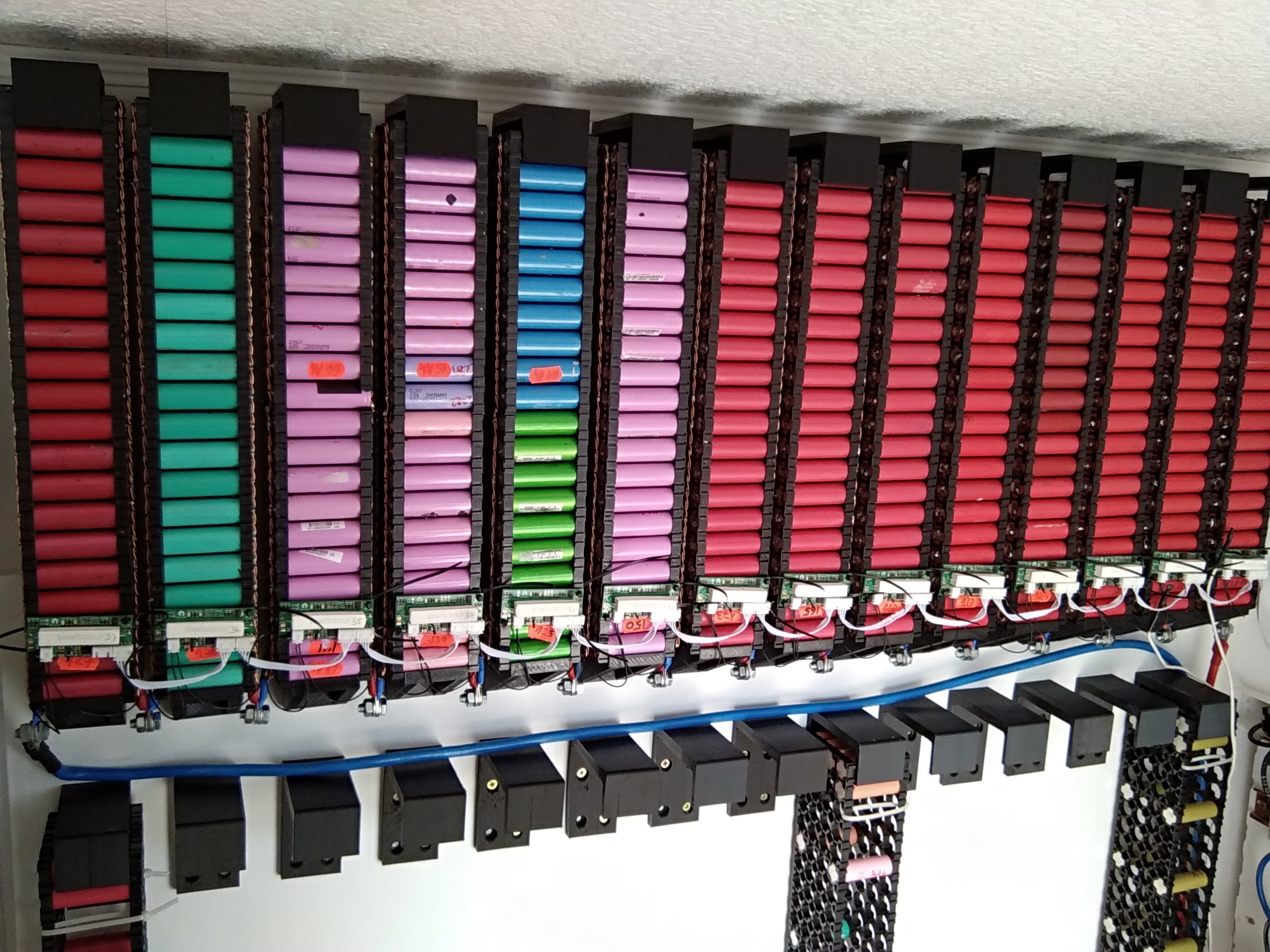

Very neat install there - a lot of power!
Hey, I recently finished all my seven BMS PCB modules and got them connected to the ESP. I can see the voltage of all the cells in the web interface and if I click “Above average balance” the BMS modules start to balance my battery. The only problem is, that the module connected to the pack with the highest voltage (the last time I tried it was 4.2V) doesn’t discharge them. Right after I click “Above average balance” the blue LED lights up, but after 2 or 3 seconds goes out with a surprising fade out. Did somebody have the same problem and knows how to solve it? Do I need to replace a specific electronical component of this board?
Thanks for any help
Tim
Hey guys,
I am very impressed about the process of this project. Some years ago I checked online for a solution for my batterys laying around. Found this but was still in the start. Thank you for that.
Is there a one layer pcb version? As I have access only for a CNC-Mill and not enough expertise/time to work with kicad or ordering pcbs. I was trying to find a simple one in the github rep. If someone has a file which is ready for CNC I would appreachiate.
I would like to build (but not to design) a single layer - “non smd/ as less as possible smd” - version.
thank you for now.
Hi, there isn’t a 1 layer PCB version. Ordering PCBs from the China shops is so easy and low cost - its just not worth milling your own PCBs. The Gerber files are in GITHUB - no need to even open or install KiCAD on your PC!
Hey,
Am sorry to not answer your question, but I would like to ask if you could share the boardlayout with me. On the photo its look like a single layer layout which I am looking for.
Thank you.
wow stuart thank you very much for your fast response. Even if its not exactly what I wanted to hear. Its always impressive to have a contact with the brain behind the project. There is a user post with a photo just some posts away and its look like a single layer design, maybe he can share it. As it is also smd there would be still some modifications to do for me.
Hi,
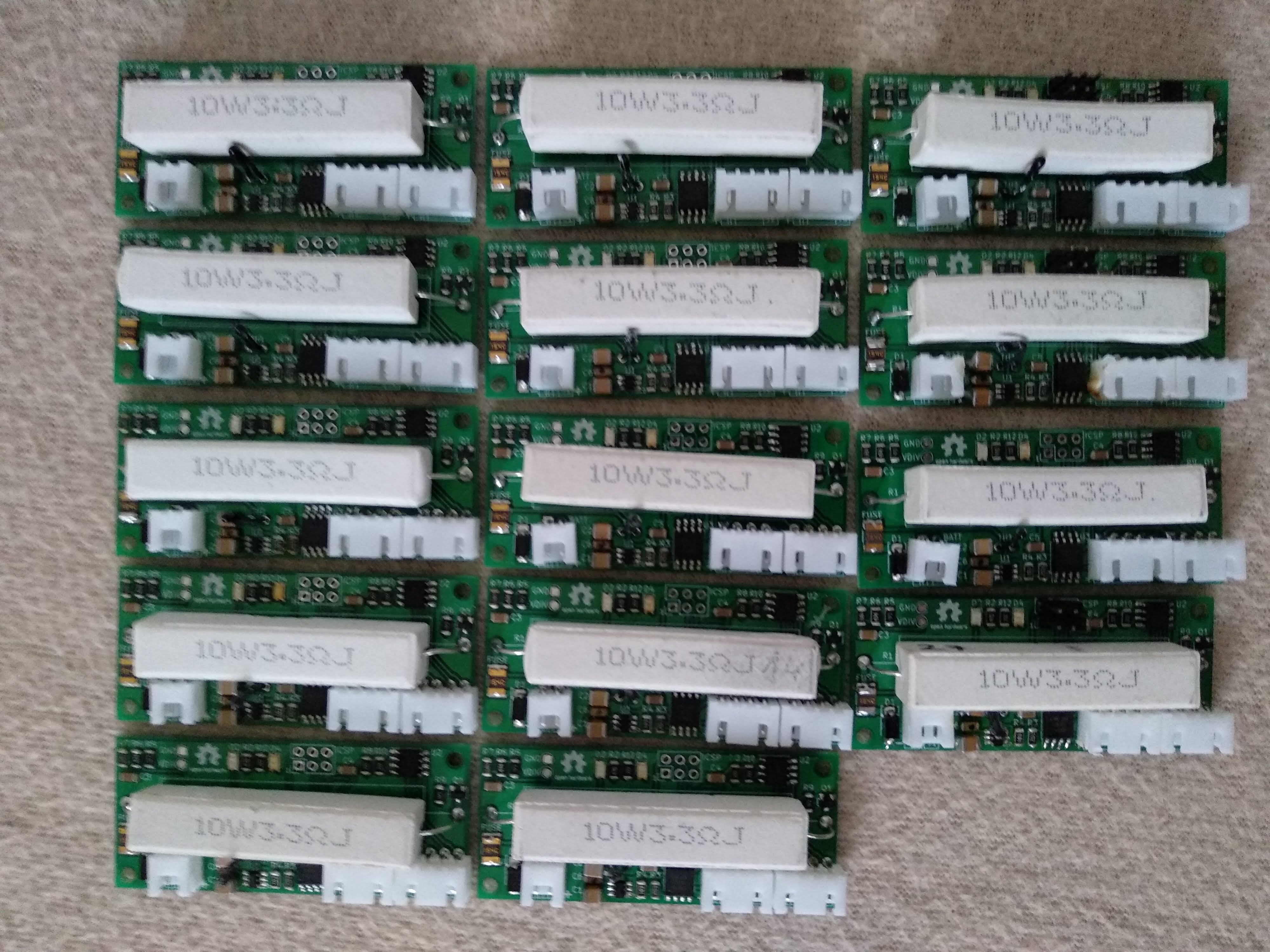
So this board was made with the Proteus program, there are some changes from the original circuit:
- The power supply part with the REG710 was replaced by a 3.3v linear regulator.
- The mosfet was replaced by an NTMFS4935N taken from motherboard.
- The isp connector has been removed.
comments:
- If the linear regulator is used it is necessary that each module has an isolated external power supply.
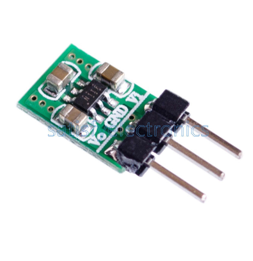
- There are three pins available on the board to add a 3.3v buck/boost module, this excludes linear regulator and external power.
- The module was made by thermal transfer method with paper.
- I do not know if Proteus exports files to cnc machine.
- I am no longer using these boards for lack of connectors and cables, I ended up ordering the stuart boards.
buck / boost converter module mentioned.
Just a comment obviously this is not my design, and using a linear regulator will mean this module will stop working when the battery voltage drops to about 3.5v, so not a good choice for a BMS.
Yes, as I said the regulator was placed until the buck/boost module arrived from china, the regulators were powered with 8v from an external source.
Hi stuart
BMS is running great the past few mounts with out a problem.
Looking at adding a current sensor hall affect sensor in the system

been sitting on a wemos D1 + wifi waiting on my current sensor to come.
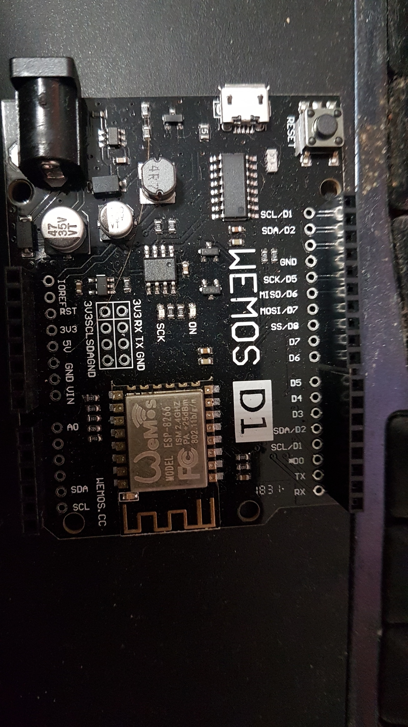
Is it possible to run the bms and current sensor via the wemosD1 + esp32 with some code modes?
As i know the D1 is much faster than any processor on the market.
What current sensor is it? There are plenty of spare CPU cycles left in the old ESP8266 for monitoring things like this.
i have the wemos D1 mini esp8266 not bad but has a tendency to not respond.
be great to add in to the charge status of batteries and voltage going to the cells along with bms balancing.
https://www.ebay.com.au/itm/50A-100A-150A-200A-Bi-Uni-AC-DC-Current-Sensor-Module-arduino-compatible/111689533182?ssPageName=STRK%3AMEBIDX%3AIT&var=413700309467&_trksid=p2057872.m2749.l2649
Summary
Are the V3 boards still available, i not sure if it would be cheaper to buy new due to postage to Australia. How do i private message you.
Hi Colin
Is there any way we could have a soldering paste stencil for the version 3 pcb because I cannot find the file anywhere.
Thank you
Hi andy
I live in Brisbane Queensland and cost me around $35-+ for each module to build myself after a few boards failed.
If you need a solder paste screen printed let me know i have a 3d printer now wouldnt be a problem printing you one