How do you have the battery terminals connected to the charger? Positive should be at the other end to negative. If that makes sense
Have the charge connected to a 300amp displacement busbar via a 20amp circut bracker.
so when discharging lipo pouches i have to change the configuration of the way its charging ?
No, just make sure the positive and negative take offs are opposite sides of the pack, not taken from same side/cell
discharge + pack 1 discharge - pack 12 48v
i cant see how its possible to not recharge on the same terminals at 48v.
if you have images then would help me picture what your trying to explain
Sorry, I’m not making myself clear.
Connect the charger and load positive to one site of the battery pack, and the negative to the other side of the pack (connections should NOT be on the same cell)
Ok will do some modifications tonight.
Cell not charged at the same time as the inverter is running. Charged during the day and discharged at night. As i have two gtil inverters 25/60v battery bank is on and day running is on my 45/90v gtil2.
first test two cell where high that. then i ran a line of copper wire across all the tabs. iv also add another xt60 loop to the other end of the cells as well so power is transferred both sides of my pouch packs.
Also my poly panels where low in power out put 230 8amp each swopped out to my mono 250w 9amp there about 8 year old
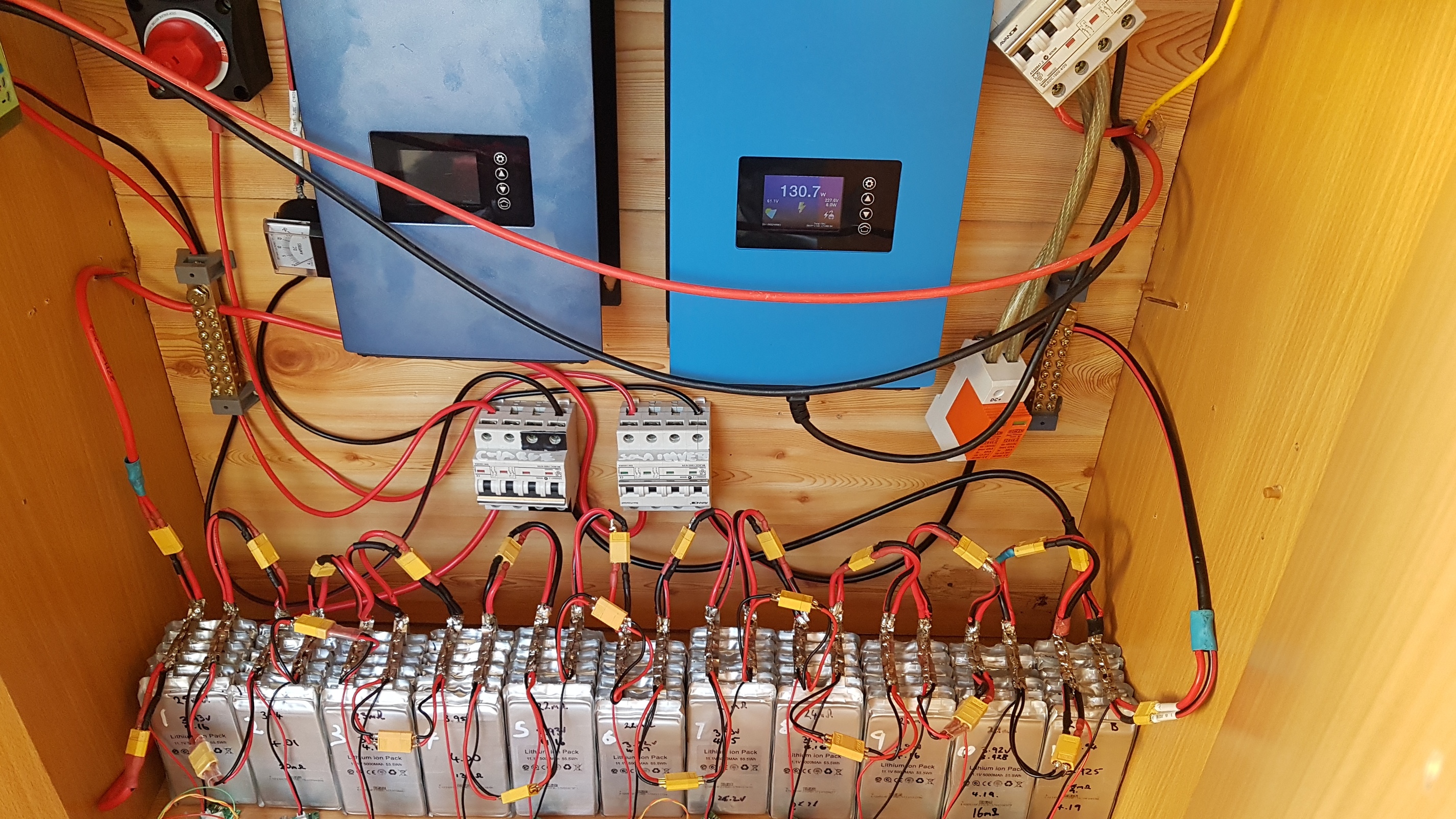
Cells running with in .01v each other. Still having issues with module 12 so dropped back to 11 cells and modules what a great day here in brisbane 36c not a cloud in the sky.
4 days since put an extra loop in the cells and running oppisit ends charge and discharge.
Hi, can anyone help me? I made 4 modules (another pcb), and when I go to configure it by clicking Provision, the module does not appear on the page, only after pressing the esp8266 reset that appears on the page, adding the second module only appears on the page when press the reset, 2 is the maximum number of modules that appears, when trying to put another one does not identify neither with Provision or reset.
It sounds like a module may have a duplicate id number - try reprogramming the Arduino code to it again to clear it out.
When you provision, start with 1 module, provision it, then add another and provision that. Repeat for the others.
Hi Thassio_Lima
i had the same problem with trying to provision the modules via Arduino-ESP8266-BMS-Controller from the web based config.
i found if i had 2 esp8266 one with the controller setup and one with Arduino-BMS-Controller-Test program setting and factory reset if any module has a number provisioning via the controller test was much easier when running more than two modules.
Thank you @stuart and @aussiegwapo I had already reprogrammed the esp8266 and attiny several times but the problem continued, I put the attiny85 chip in an external programmer and I saw that Data memory always had a code even after cleaning the chip and programming again, only after manually clearing that part of the memory that the modules have received a new address.
Now the four modules are already working, I just have to make the other cards and connect everything.
I am using a 3.3 regulator provisionally but then I will replace it with a buck / boost module.
Glad you got it working.
hi, i know this is a DIY project.
I m not able to solder at all. There is some way to have full shield and maybe contribute into coding?
Hello Fellows,
I’m new it this community, but I find it pretty interesting and helpful. All of you are doing great job.
I don’t wont to dilute your conversation, but I have fey questions about this great product that you are creating hire.
- Is it possible to connect this BMS whit my Hybrid Inverter SolaX SK-SU3700E? Normally it is design to work whit others BMS’s like in LG Resu and ZTE Pylontech.
- Is it possible this BMS to operate contactors to isolate the battery from the inverter in the event of a battery issue?
- SolaX inverter also can read temperatures on a separate port, is it possible to take out this signal from DIY BMS as well?
- I’m not able to find PSB v3 (sep 2018) files in GitHub, can someone send me a direct link.
- That parameters should I use when order PSBs to be made? (PCB Thickness, Surface Finish, Copper Weight and so on)
Thank
Kiril
Hi, I’m new to this forum but I’ve been watching this thread for a while, getting some tips.
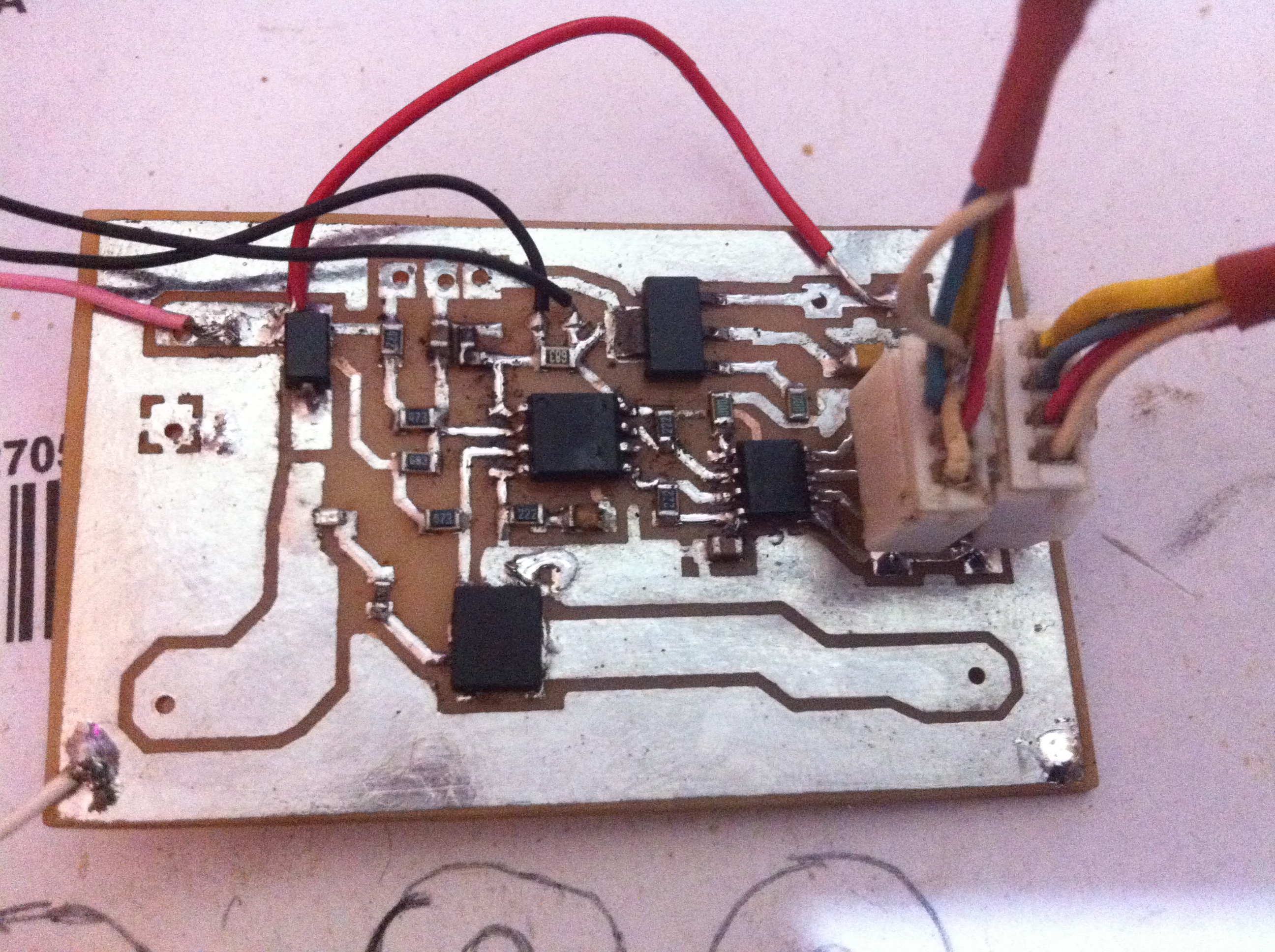
I’ve ordered some v2 boards and am waiting in anticipation to receive them, but I was flicking through some schismatics on my PC and I came across this. This circuit will take the power from a full cell and send it to the next cell in line instead of wasting it through a resister as heat. The downside is the monitoring software of the batteries through your WiFi is not included.

Having done lots of research into active vs passive balancing, active balancing is not worth the extra cost in 99% of situations and is less efficient than just doing passive balancing near top of a charge cycle. Take a look here for more information:
https://www.eevblog.com/forum/projects/high-efficiency-bms-project/msg1815428/#msg1815428
Dear Stuart,
I’m watching your video about the BMS PCB you’ve created. I would like to tell you congratulations. I would like to assemble batteries to store energy. The batteries will be charged by solar panels. Your BMS PCB will integrate very well my equipment. So, I am a French energy engineer, but I do not know anything about electronics and coding. I would like to ask you if it’s possible to help me, use your BMS. You have uploaded all files to build the BMS PCB. But I admit I don’t know which file to use.
Can you please explain to me the following things :
1 / Please, tell me how to install the Arduno code in the BMS PCB.
2 / what devices will I need for setting the BMS and retrieving data to my PC, load the code on the BMS PCB.
3 / Please, I need a tutorial that explains the operations from A to Z.
4 / And finally there are the different variants on the use of discharge resistors ?
I hope to receive answers from you to my questions.
Kind regards
Charles
[Moderator: edited to remove duplicate text]

Stewart do you think it would be possible to run the diy bms controller on a esp32?
@Jman_brosef Yes - people have already run it on that
Is there a repository for the code ported to a esp32?