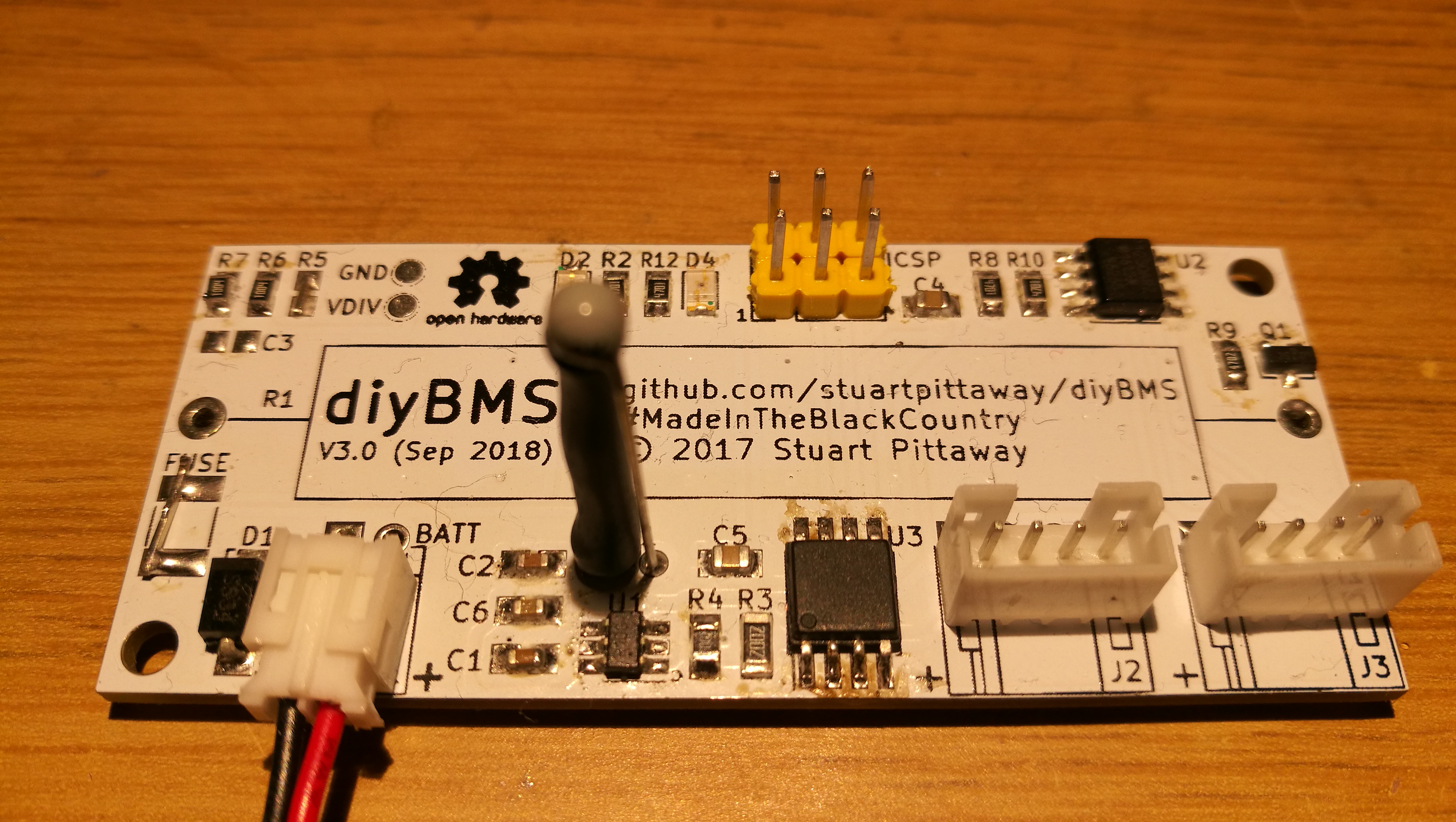
I’ve got 17 spare DIYBMS v3 (Sep 2018) blank PCB’s - happy to give away if you pay the postage.
Perhaps split into 2 lots of boards? Send me a private message to arrange.
I’ve got 17 spare DIYBMS v3 (Sep 2018) blank PCB’s - happy to give away if you pay the postage.
Perhaps split into 2 lots of boards? Send me a private message to arrange.
Hi stuart
Got some more parts for the V3 have one almost rebuilt and still waiting for ADUM1250 to come do you have a close up image of the completed boards you have just want to confirm iv got everything in the rite place and can track down where my other 2 built bms boards went wrong and why one has no activity but other has Attiny85 activity but no communication.
I used a 47k in the updated schema. Note that I didn’t populate C3 as its optional.
@stuart i can see on my boards c3 runs to C5 same side what is the option to populate that connection do ?
why when i replay to post it dosnt attach to name in post
but if i reply on my phone it replays
The difference is the clock speed. The 20su will work just aswell
I modified a existing design
18650 Pack wall mount found on #Thingiverse 18650 Pack wall mount by CheetahGod - Thingiverse
Yes. Differs in the clock, but it is the maximum speed - 20Mhz.
It sets 8MHz internal clock so it can do something. At least blink, etc.
Other differ in working voltage - from 1.8V … 
Nobody to test another TINY85?
@eSumo you will be fine with the 20SU - when you program the code the fuse will set it to use 8Mhz anyway.
The only problem with this model - the voltage cannot go below 2.7V, but that isn’t a problem as there is a regulator on the circuit to provide 3.3V.
Thank you Stuart - I expected answer to look for a problem. I wanted to be convinced.
And It paid off! It’s resolved! 
The problem was in me…  I did not install the thermistor because I want it on the side of the links to be between the cells. If themistor absence, Tiny did not reset. That’s how I explain it.
  After the thermistor is mounted, the modules are working! All five!
No matter - 85V 10SU are already on the way…
Thank you once again. Without this answer, I would not find a problem.
I will continue the next 9… 
I like this! 
Hi eSumo
i had a few problems with modules as well. i put it down to the boards and some faulty components after building two more boards took the program with out a problem but they fail to communicate with other boards and wemos.
so i took off some components that i known that where good and built to more again if that didnt work i was just going to stop at 10 modules but now have all 12 up and running.
Been a long process about 2 months waiting for parts to come in.
Oh yeah. if i read carefully… Problem with reset and thermistor here was written…
I haven’t had any issues with my 7s boards. They have been running for months working great.
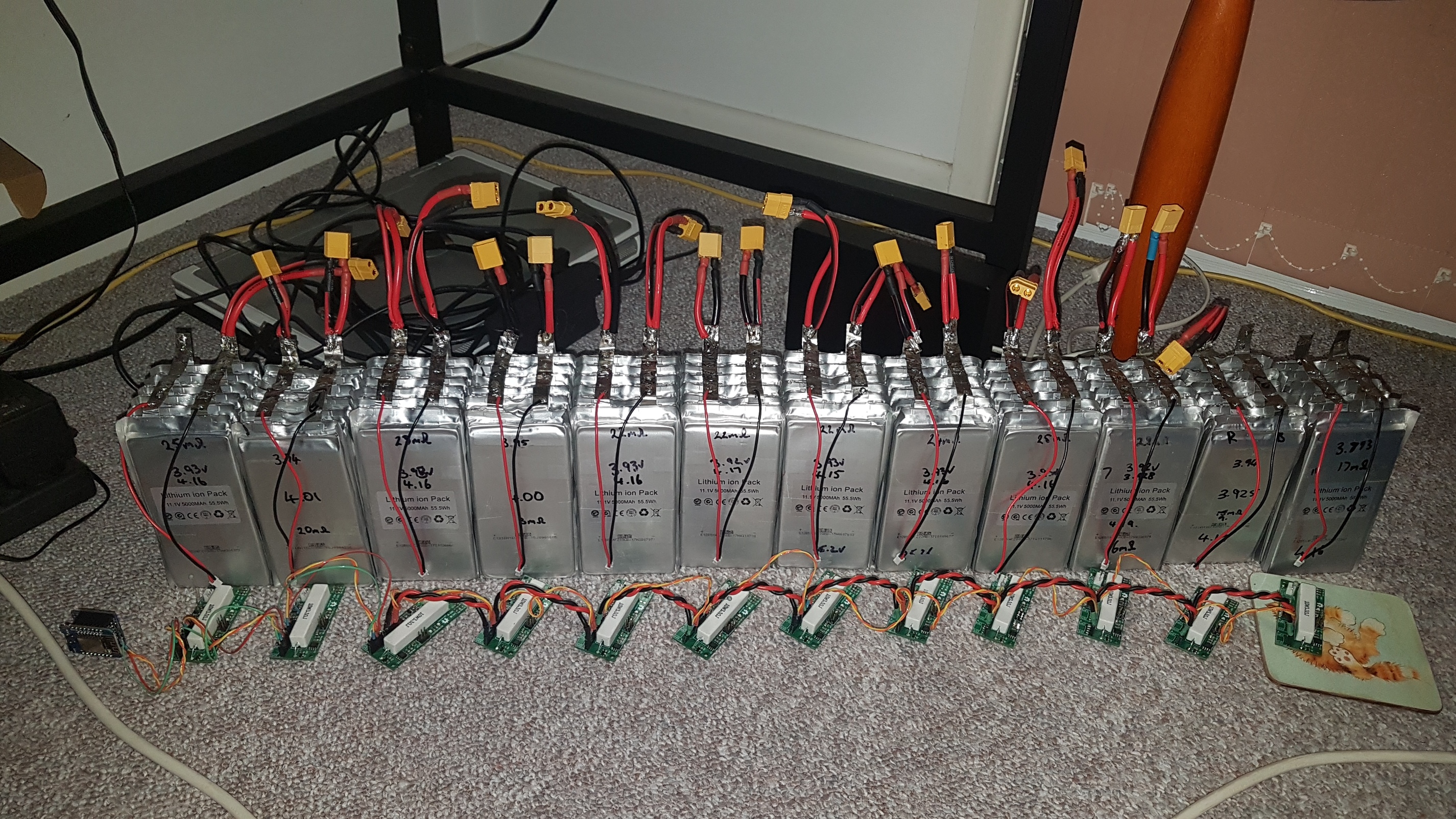
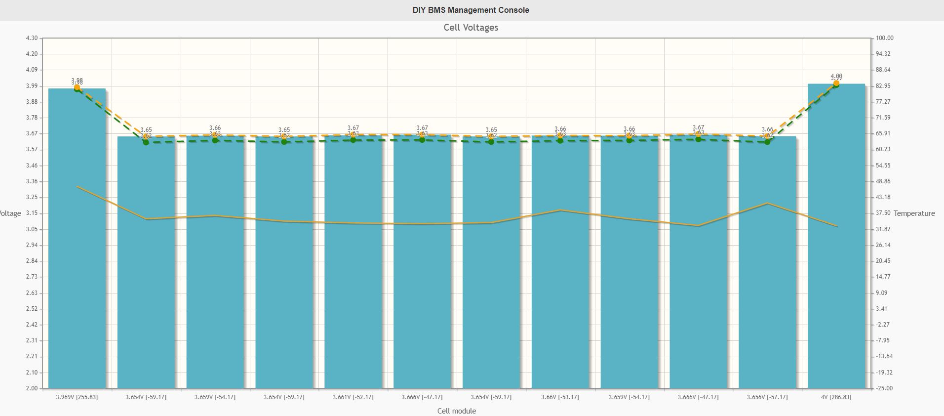
Hi stuart as of 5am this morning after 13hrs of balance last pack 4.2v to 4v was a long process waiting from my charger each cell was 2±Ah each for a 10Ah pouch as new 11Ah+ will start setting up full connetions waiting for first night test run on my GTIL2 at 48v on battery. Modules are disconnected at time of photo as cells are .01 to .05 of each other. Will see when charging this weekend when im home how it all runs on a 10amp charge. Very low for these cells as each handle 5amp charge
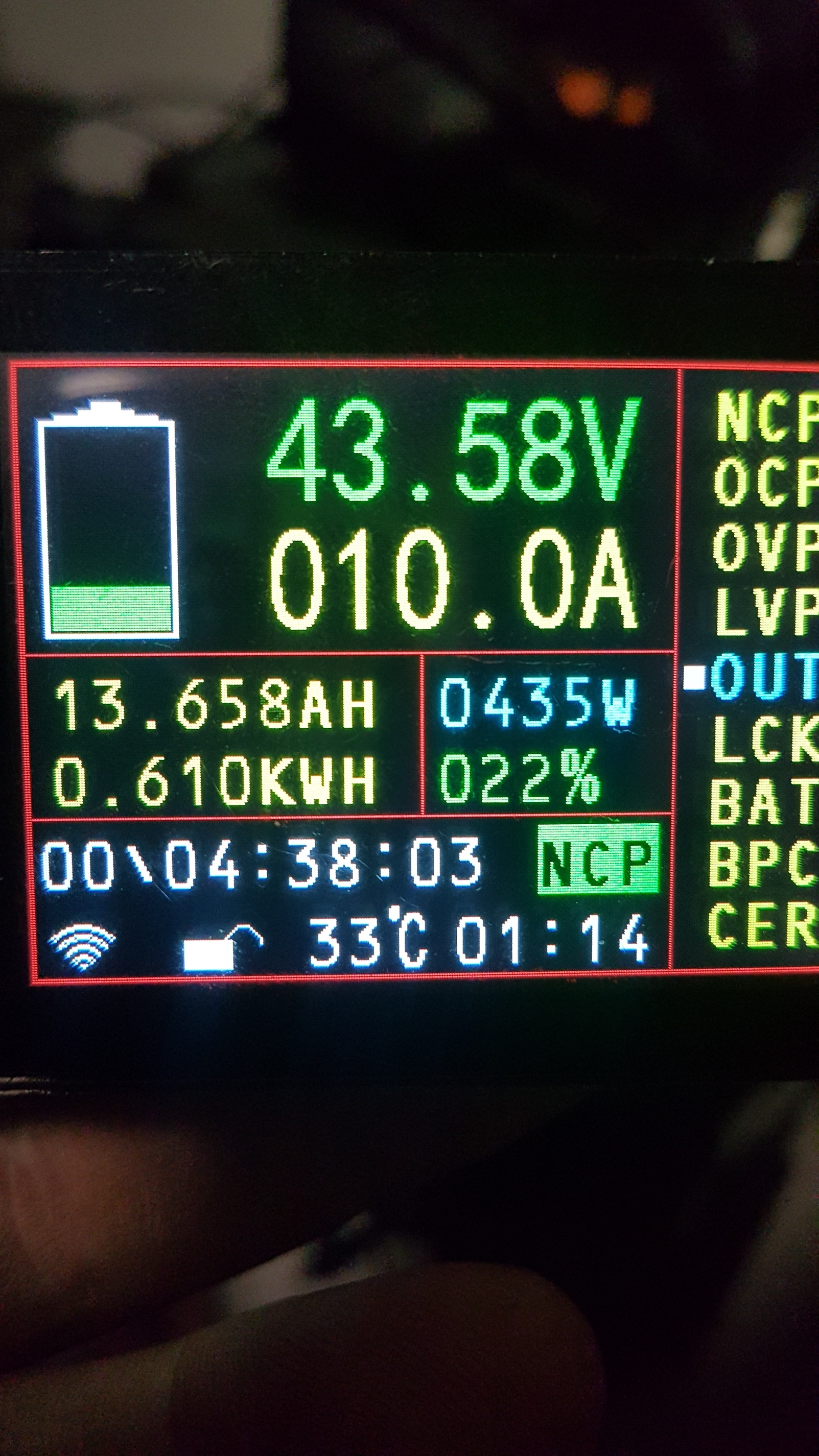
Is the display from your charger or from your ESP BMS?
The display has an esp built in to th back of the device. Monitors from the shunt that controls SSR relay. But the cheap 10a 60v to 1.65v/32v step down fried on a 24v test was really pissed
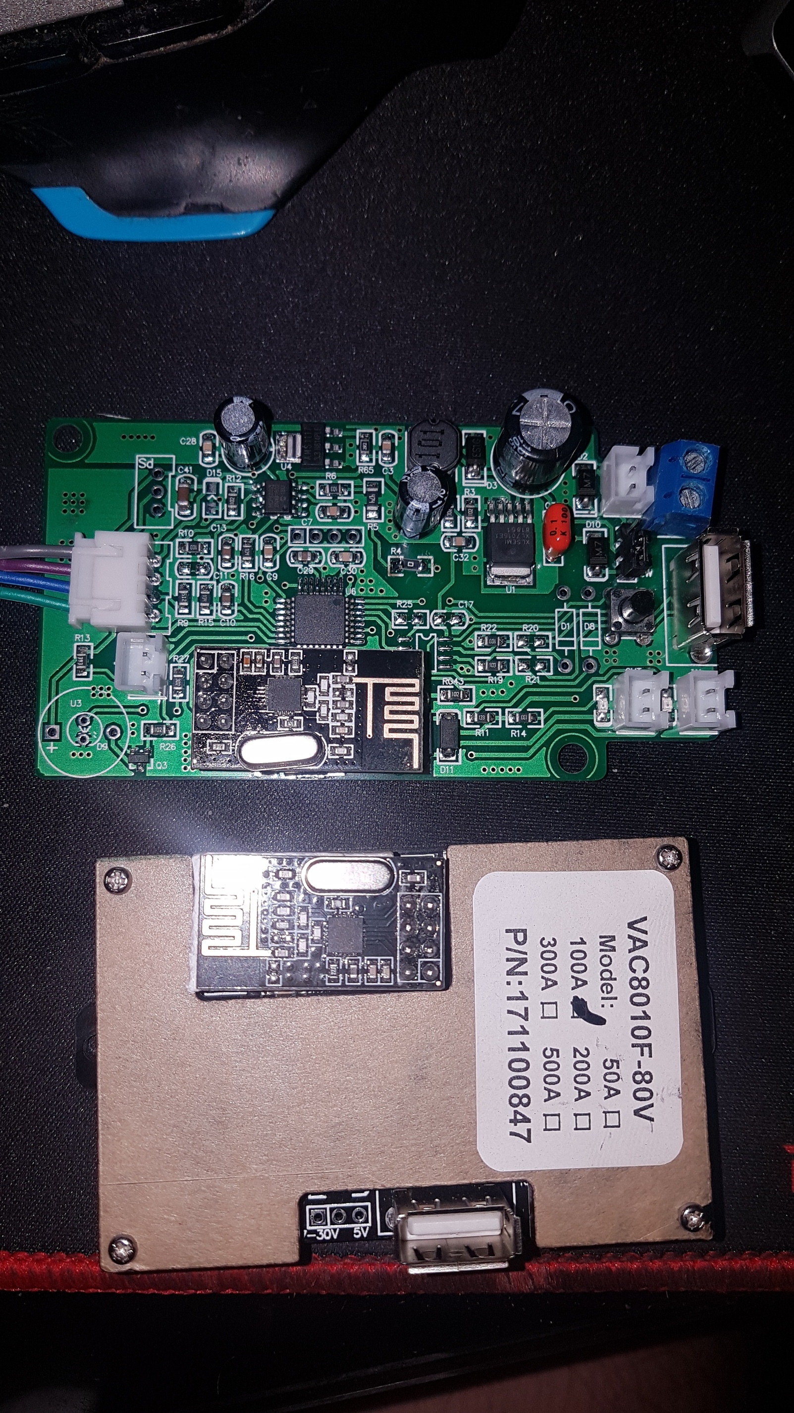
thes are the esp modules the unit uses to communicat from shut to the screen. Via 8 pins all i can say over 48v the shunt is caluclating 4v out not sure if i can correct this error.Have you calibrated these two cell modules? Are the resistors the same as the other modules?
hi stuart
yes all the resisters are the same and have been calibrated.
its strange that pack 1 is + and pack 12 is - from my experience the packs should drain evenly.
waiting for the packs to recharge to do another test