do you have calc the bypas ?
Max 4.2V / 2Ohm = 2,1 A
Stuart did you ever read? I just heard that 2 ohms already at 4.2v can be a problem because it is 2.1A in the maximum.
The circuit diagram specifies 3.3ohm resistor which is 5.3W @ 4.2V and 1.27Amps
If you have decided to use other sized resistors, you may need to adapt the other components like the fuse.
1 Like
I know nothing.  I did run it in bypass for a few hours yesterday.
Stuart: I just wanted to point out to Chance Schrader that the 2ohm as R1 can lead to a problem under continuous load. Both for the board also depending on what he has installed as a backup.
They are 8v 2 amp hold and 3.5 amp reset fuses.
At 2ohm the load is just over 2 amps - it would be rare to charge the cells up to 4.2V so at 4.1V balance it would be a fraction over 2amps - I doubt that would cause a problem with the fuse.
Hey Stuart and others, I am wondering how you guys charge your liions.
Personally I am running 6s, so hobby chargers exist.
Stuart you said you’re running 14s? how are you doing things.
Also I saw a mppt 70a picture in the thread.
What kind of current limited power supply are being used around here ?
Hey, I’m a student and currently working on the DIY BMS. Already had a lot of fun building it. Thanks to Adam’s videos I got to the point where I uploaded the Arduino-ESP8266-BMS-Controller.ino onto the Wemos D1 mini. I connected my pc to the “DIY-BMS-Controller” hotspot but unfortunately put in the wrong password. So of course the Wemos didn’t connect to my wifi, but it also stopped showing up in my wifi list. Although I reuploaded the Arduino-ESP8266-BMS-Controller.ino the Wemos hotspot didn’t show up again so I couldn’t put in the right wifi password. Does anybody know if there is a way to reset the Wemos? Or do I have to do something else to make the Wemos show up again as a hotspot in my wifi list?
I’m very thankful for any help!
– Tim
1 Like
I have had a similar problem. The wifi details are not over written when you upload new firmware.
This should help:-
https://www.esp8266.com/viewtopic.php?t=8204
Ian
Hi @Darulin , as mentioned by @ian above you need to look at clearing the SPIFF flash memory
There is also a guide here
@blob I’m using an AC-to-DC power supply along with a CC/CV charger.
If you are still stuck try a different firmware completely like Tasmota. The BMS firmware should really fall back to AP mode if no wireless connection is actually made.
this is a script i have used to clear EEPROM Clear_EEPROM.ino (951 Bytes)
Thank you all very much! The command line mentioned in your link @ian together with the esptool from the post which @stuart sent got my wemos working again. Now I’m happy to continue the project 
1 Like
Ok, what step down devices do you use to power lower voltage stuff?
Do you need 56v for a specific application?
I don’t its fed into an inverter to power the house!
Hi all.
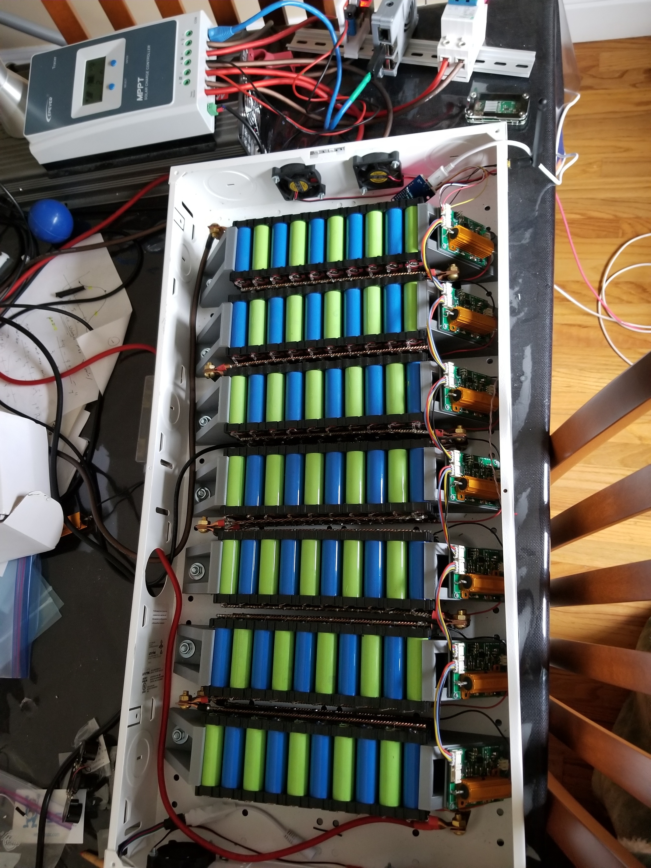
I like DIY BMS and decided to build for my 14S120P 18650 pack.
After nearly 2 months waiting for the parts I now build the first 4 boards and controller with Wemos D1 mini. The controller is probably OK but the cell modules not… 
After week I found out that I ordered 50x ATTINY85-20SU! 
Should be ATTINY85V-10SU… 
It is why the cell module did not do anything? No light, no blink, no comm… 
I see only one diff - low power…
Thanx…
Sorry for my English… .
Jman where did you get the 3d templates for the 18650 pack holders. Can you give us the link?
Best regards Dirk