Are you still using your Alibaba lithium ion battery?
I did some numbers and I can’t bet their prices per kWh… so I am considering buying directly to them.
Have you ever measured the battery capacity?
If you have any info about the performance, state of health evolution and capacity please let me know!
hi Adrian - yes I still am using them. I bought a couple different types over the years I bought LiFep04 cylindrical batteries( +5years ago) and prismatic ( last year). they both worked as fine as expected the capacity is as expected the green one are cylindrical batteries so you can not charge very hard or discharge very hard. they list 40amps but like every thing that manufactured in china that utmost limit you be safer to to it at only 1/2 that rate. the prismatic battery has charge as discharge rate of 400 amps I only had this one a half a year but it also works as expected though the BMS gives be a bit of problem nothing serous i bought it for a windgen but it too sensitive to volt spike and puts it self in protection mode so i would not recommend these batteries for wind generation only solar. supposedly 2500 cycles at 100% DOD i try to run them at 60 -80% so the life cycle will be 5000ish so have to get back to on that in a few more years but currently they seam fine.
I also bought NMC batteries they are very cheap to buy about the same as lead acid of the same ah but also they have the same lifecycle as a lead acid at 100% DOD 300cycles. but for those you just buy more of them say you want 4kw of storage you buy 8 -12 kw it cost about the same as lifepo4 just do not cycle them very deep 30 - 60% and you should get the same lifecycle as the lifepo4 but the added benefit of big bank if you need it in an emergency
avrdude: stk500_recv(): programmer is not responding
avrdude: stk500_getsync() attempt 10 of 10: not in sync: resp=0x03
Error while burning bootloader.
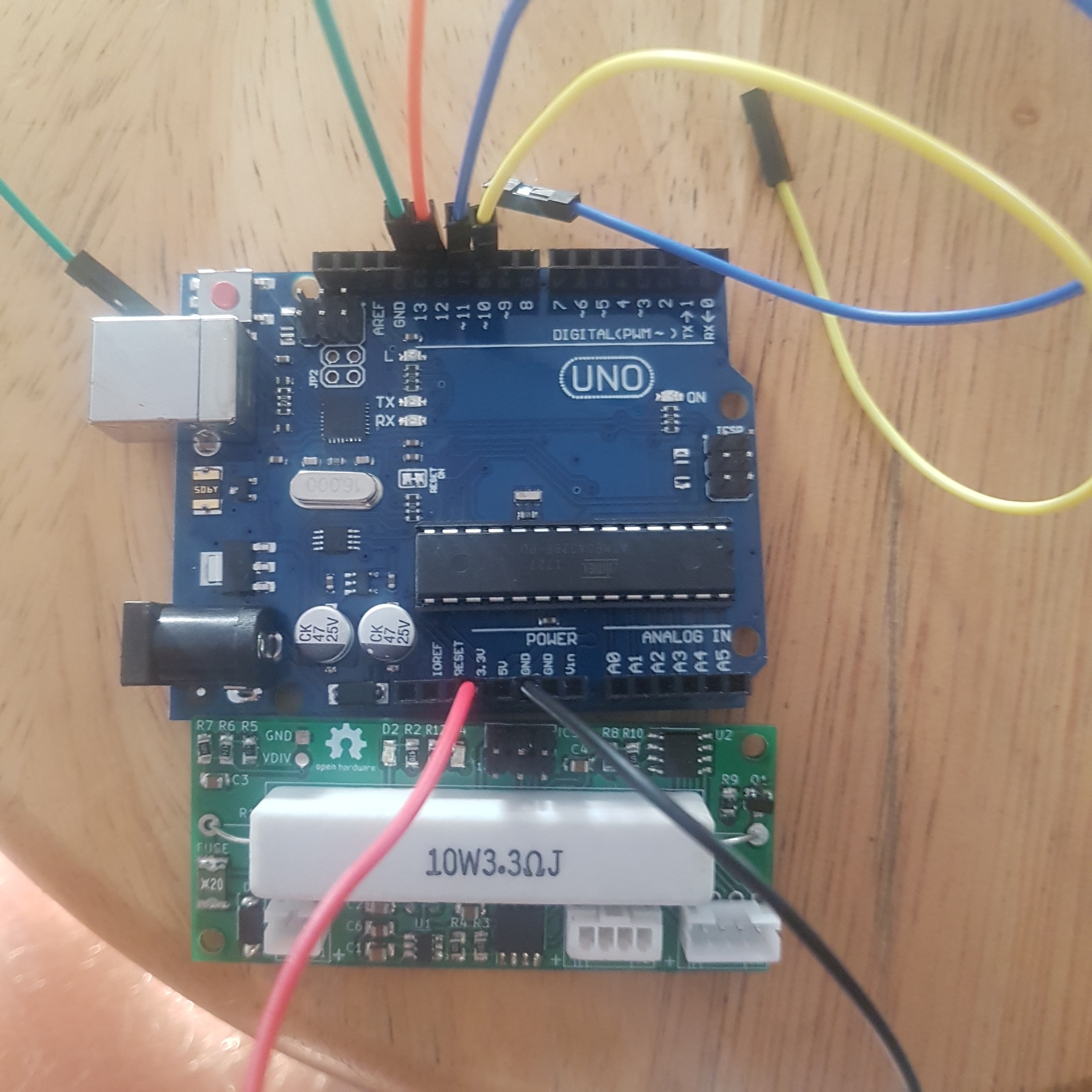
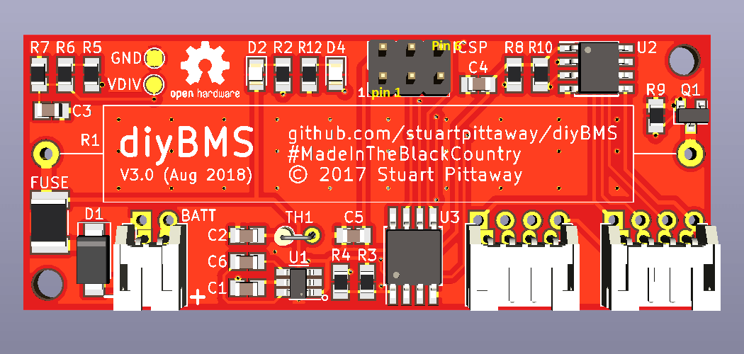
From the ISCP header, pin 1 is bottom left.
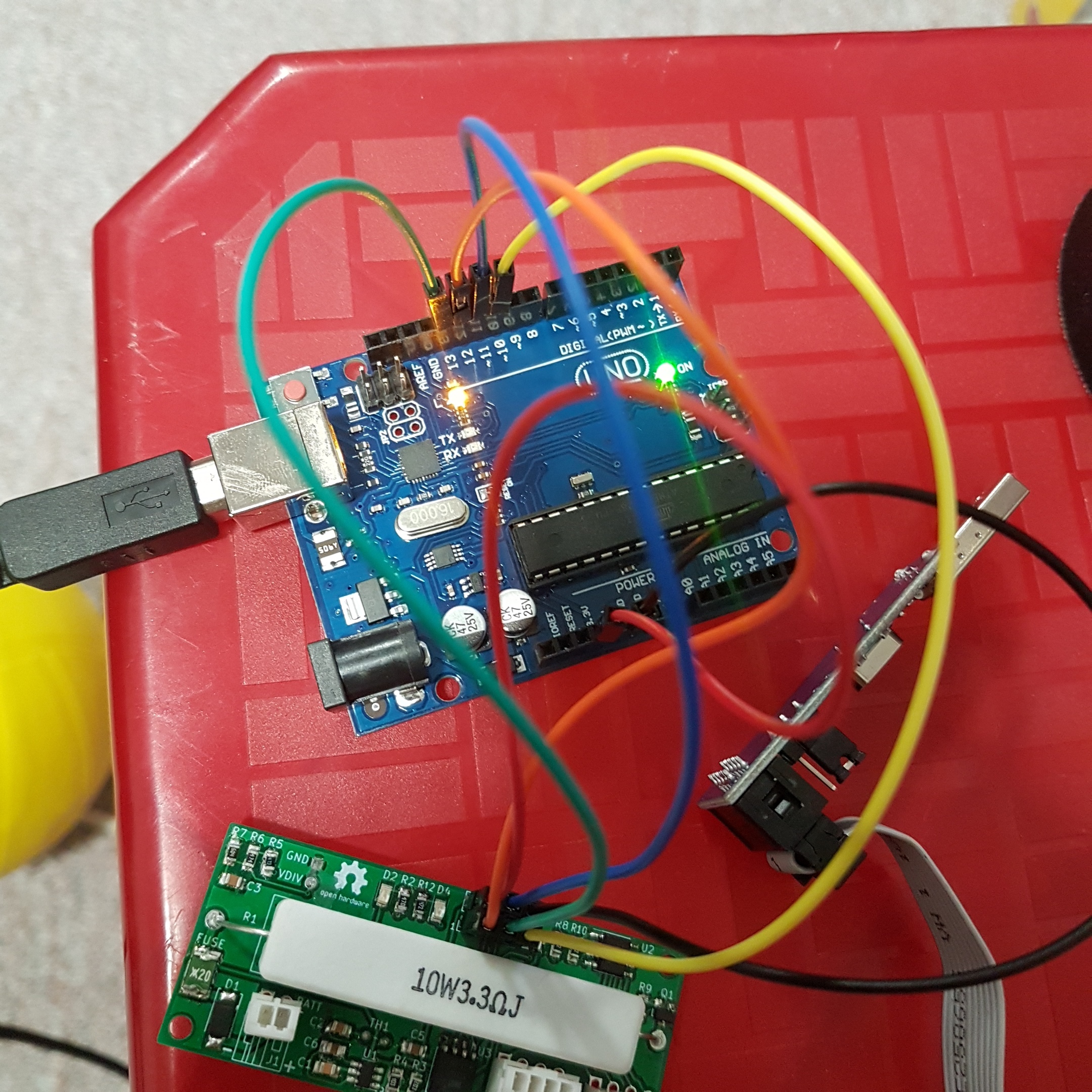
Connect pin 1 of the ICSP header to the MISO pin of your MCU. Orange Dig 12-PB4 (MIS0)
Connect pin 2 of the ICSP header to your +3.3V supply on your board. Red 3.3V
Connect pin 3 of the ICSP header to the SCK pin of your MCU. Green Dig 13-PB5 (SCK)
Connect pin 4 of the ICSP header to the MOSI pin of your MCU. Blue Dig 11-PB3(MOSI)
Connect pin 5 of the ICSP header to the RESET pin of your MCU Yellow Dig 10-PB2 (ss)
Connect pin 6 of the ICSP header to your ground (GND).
On the picture they go…
2 4 6
1 3 5
biggest problem is ISP AVR programmers dont like windows 8.1 to 10 what a joke
Build 12 boards out of those 12 only 3 have problems will do testing to track down where the problem is
could be due to chines attiny85-10su but all caps and resisters have tested fine but will get a few more components build few more boards to cover the 3
I’ve ordered some V3 small PCB and now I’m trying to buy all the components.
Looking at the BOM file, C5 is 0.1uF Polarized but I can’t find it on AE or ebay… can anyone provide a link?
out of 12 modules i have built only 3 of my modules have problems which im trying to figure out why they wont run but will take the programming.
i didnt buy polerized caps C5 cap will test what the other 9 modules test via componants figure out what my problem is.
my problem is i can provision 9 modules using wemos D1 mini r2 with 2.2k resistors but when trying to provision 10th and so on no communication like connection fail on serial port
I build now 8 working modules V3 for an 24V600Ah 6P8S batterie.
Could you please help me with your experiances?
Why is there this yield in your software to slow down the loop?
is it to give the modules some time to do their work before next readings are done?
But reading the modules is anyway done by timer every .5 seconds right?
I run it on an ESP32 WROOM and no yield… therefore I care for time and OLED in the loop.
I wrote some parts of the software new and gave it a different GUI. I can offer to post it if someone is interested in the software. but it needs still lots of testing and optimization.
I use additional SDcard and OLED display, the GUI loads some JS and CSS from SDcard for table and design. And I run the diyBMS in offgrid and offline conditions so it cant load any flies from online sources.
I added under and overvoltage alarm and cutoff routines to protect the batteries and give alarms and if under or over voltage decreases resp. increases it will disconnect the loads or charger.
I used GP_IO and some hardware to realise these functions.
It turnes out that I get lots of false alarms.
espacialy 2 modules deliver them, I get sometimes voltage readings that are out of usual range.
usual range is 3358 to 3.360
most mistakes are around 3455 to 3474
sometimes I get ~ 34559
rarely ~50175 and ~ 0897
Do you have any idea what goes wrong?
I could oversample by timer, using the alarm function, and only if the value, in question, that issues the alarm stays for, lets say 20 seconds, the alarm will be set to action.
But I would like to find the reason why there are these readings out of range and solve the problem this way.
I had the same, from 9 modules 1 was not to get to work, even that I changed Adum and ATtiny and double checked all other components… maybe I will try to look for it later again
same with you the green LED was blinking and ATTiny took program and fuses and was verifyed with ATMEL Dragon, I spend some frustrating time with it. I checked the I2C tracks…
but the other 8 modules work, only I get, mostly from 2 of them, some crazy voltage readings now and then…