@ebsol Is your design posted anywhere? I’d be interested in taking a look through it if so. I’m using bit-banged serial as well but the ATTiny85 does have some hardware support via the USI. Why did you choose the ATTiny13A?
@stuart Curious to hear more about why you’re thinking about moving to a daisy-chained protocol. One aspect of the daisy chain that I really like is that there’s no need to provision cell modules- they just assume an address based on their position in the chain. I had initially tried a serial bus approach (sort of like I2C) but my custom solution was not very reliable and I ended up reworking the communication protocol. It has been very reliable with the daisy chain approach so far. On a side note- I’ve been looking at your hardware designs and realizing they’re much more complete than mine. If you were to make a version with an ADUM1201 capable of being daisy chained I’d be very interested in trying to run my firmware on it. I had been thinking about redesigning my cell monitor board but it probably makes sense to reuse as much of your design as I can.
Not at the moment. I will when I’m happy that it works reliably. At the moment it all works perfectly until I put the battery pack under heavy load into a switching power supply. Then I get occasional unexplained errors or lockups. I didn’t want to release it until I know I can solve it.
Does yours work flawlessly when the pack is under heavy switching load?
My goal was to make each channel as small and cheap as possible and having the lowest possible power consumption. Plus you can then fit pretty much any pin compatible ATTiny device you could get your hands on with little or no code changes. I’m beginning to question my decision though. The code completely fills the chip leaving me no space to do any debugging. I’ve temporarily switched to using an ATMega328 on each channel while I try to debug my issues.
@scttnlsn The i2c design appears to be working well for most people, a few have reported issues with interference - which is to be expected for i2c cables.
I like the daisy-chained method as it removes a lot of complexity for the end user in the provisioning of the addresses for each module, it also takes some of the load off the controller as it no longer has to sit there polling each cell in turn - but that’s a minor point.
I have a 2000W inverter (2000 Watt 12V Pure Sine Wave Inverter | PST-2000-12 | Samlex) and under heavy load I have not noticed any issues. I have noticed I sometimes lose a packet or two when I’m running a DC water pump, though, I suspect it may be due to the physical vibration and my poor quality dupont connectors. Been thinking of redesigning my cell boards with JST connectors like diyBMS.
That is good news. Since our designs are quite similar, that give me some confidence I will be able to track down and fix my issues.

High again. While some people seem to have little or no problems, I am still hitting one road block after another.
I can provision 1 module with my wemos. When I plug in a second module to provision, the wemos shuts down. I have about 4 working module and it does not matter which ones I am using. Any idea where the problem would reside?
Your very welcome Josh
How are you powering the wemos? It feels like a short circuit or insufficient current for the i2c cables.
Thanks for replying Stuart!
At first I had the wemos powered through the laptop USB. I have tried switching it to 1 18650 for power.
Also, I have been powering the modules wired to 1 18650.
If you are daisy chaining the +/- cables from the wemos to the modules - its possible that the wemos cannot provide enough current for that - there are a lot of wemos units out in the wild of varying build quality and components.
Hello BMS friends,
i was lucky to find this bms projekt. One question to the developer. I have seen the big resitor on the battery moduls. If your battery is in disbalance, do you adjust the high level battery to the low level voltage and produce wasted heat? Or do you take the energy from the high cells and feeding the low level batterys?
Hope that question was not to stupid… have a nice day.
bye Falko
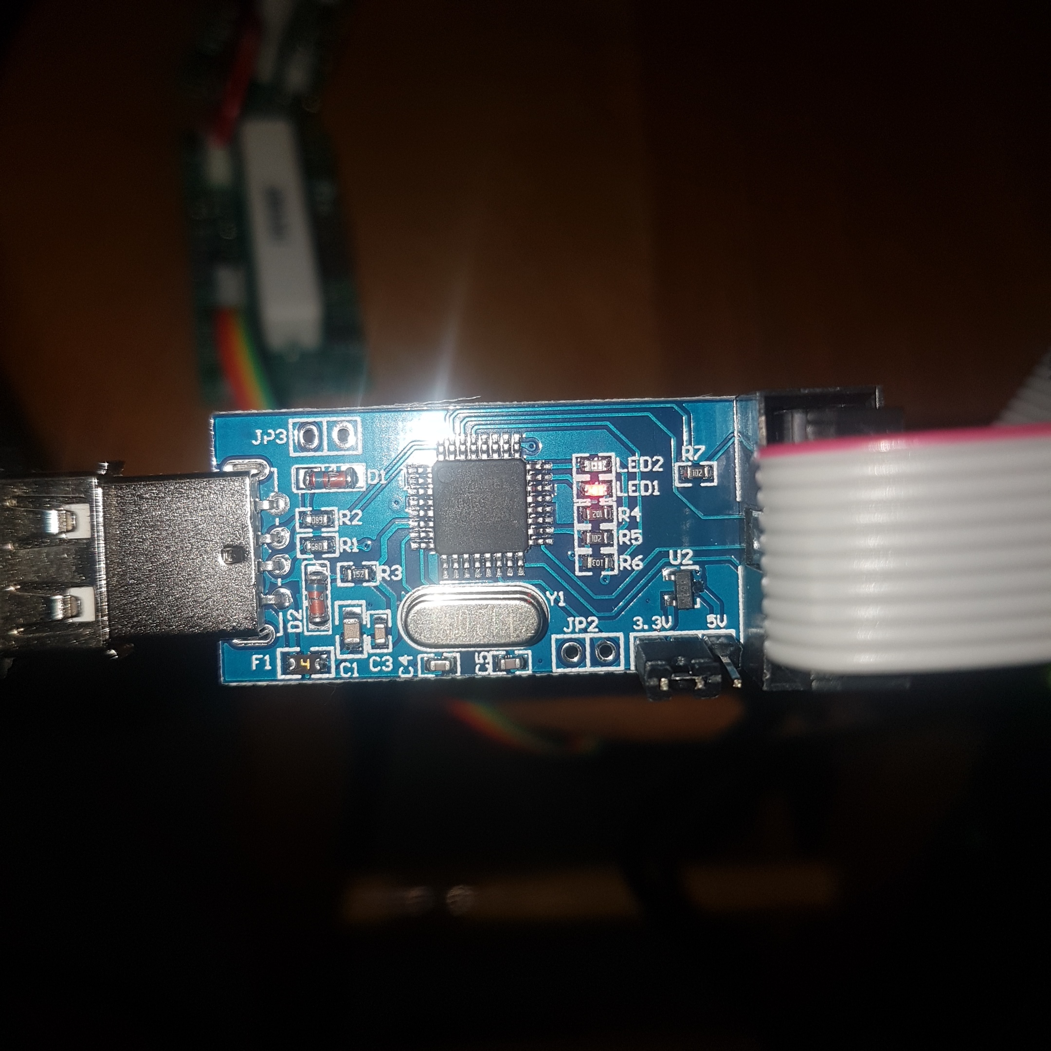
does any one have any problem getting ISP programer soon as its pluged in to the module isp programer dropps out
Just to check you are removing the module from the battery and i2c cables - just the ISP programmer should be plugged in.
ISP also needs to be running at 3.3v not 5v as some are.
I just un boxed my isp programmer didnt know it had to be 3.3v pins. When running the burn program what the board setting eg isp avr, ect
That really depends on what you have brought - is there any instructions with it?
packaging duintech isp programmer for duintotech & avr and a 10 pin to 6pin
I guess with an isp pogrammer dont have to burn bootloader like you would have to do in arduino
Try using that with the USBASP settings in Arduino.