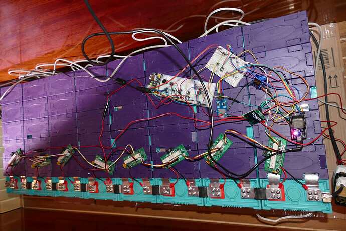
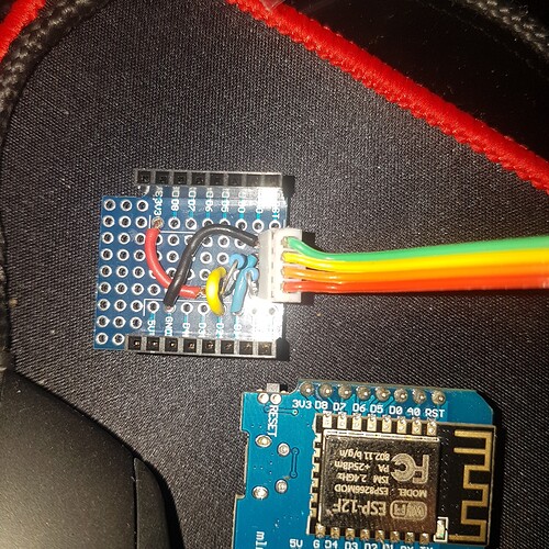
How are you powering the +/- connections to the modules (not the battery side?) each module will need 4-5mA to drive the ADUM chip.
That may just be a code bug - are these readings 65535 / (0xFFFF) in which case the i2c didnt read correctly.
There is no error correction or checksum in I2C transfer, right?
In most cases it reads 34559 what is 0x86FF…
For now I power the ESP board by 5V and from there I get the 3.3 V to power th I2C Bus/ ADUM
Do you think its better to provide the 3.3V for I2C bus from a different external source?
I can try that, maybe the ESP is short on power?
In the past ive had alot of problems with breadboards, so maybe make a shield or perfboard. It could be one connection on a resistor is bad and makes it fluctuate from time to time…
Hi and thanks!
Yes I will build a shield and get rid of these breadboards.
Is not the components on the breadboards that troubles me most but it could be the external power source that is traced over the breadboards to the ESP. And I will change the power via I2C bus for ADUM´s from ESP WROOM to external power supply.
The rest of components on the breadboards is the alarm LED´s and piezo sounder that is tested on GPIO for alarm signals at over or undervoltage.
thanks Oliver
Hi Chrigu,
how are you going on?
how about your voltage readings? I hooked 8 boards to 8S batterie and get now and then, beside the usual variations of the cell voltages, readings of 34559 what is 0X86FF ?
I saw there is a CRC in the code of the module but its not used as I realised.
I could not find any bug in the code that causes this reading. Stuart told me some guys get 0xFFFF as bug reading…
So I added verification code to eliminate these readings from processing.
Oliver
Thats used to store EEPROM contents using CRC checksum.
Buenos Dias
Siempre me ha encantado cacharear en todo, ahora por desgracia tengo tiempo y inquietudes, estoy reciclando baterias para que sean alimentadas por placas solares que ya tengo instaladas. Quiero probar a construir mis propios BMS comprar un ecosistema como Battriun no es divertido.
Good morning
I have always loved to cacharear in everything, now unfortunately I have time and concerns, I am recycling batteries to be powered by solar panels that I already have installed. I want to try to build my own BMS. Buying an ecosystem like Battriun is not fun.
Hi Stuart,
I got my I2C problems finally solved, I had to play a bit with the I2C pullups, as I used additional an OLED display on I2C bus, that somehow also influeced the I2C transmissins. Now I set the I2C resistors both to 4.7 K (quite standard) and I get rarely wrong numbers by I2C. 
thanks Oliver
So I am having an issue. Was wondering if anyone can point me in the right direction. The only thing I purchased from aliexpress was the thermistors and the wire wound ceramic resistors. everything else came from digikey. I have soldered up all 7 of my boards and they are from the revision 2.1. The issue I am having is only 3 green led lights will light up the other 4 will not. They are all being tested with the same test battery pack. I am only getting .7 volts out of the REG710NA-3.3/250 vcc side. the ones that light up are getting the full 3.3 volts. I have no idea what is wrong. I have ohm everything up and they come back the same on all the boards but voltage isn’t coming back the same. I dont have a scope or I would look at those values. Any help would be appreciated.
Hi,
- take a magnifyer and check for solderpearls and shortages.
- check if the chips are in right direction?
- what ohm is between + and - batterie connector?
- when connected to batterie is GND at pin 2 of REG710 ?
- when conected is VCC at pin 3 + 5 of REG710?
Oliver
As suggested, its got to be a soldering issue if the other boards are working okay. Perhaps take one of the failed boards and try the “frying pan” soldering method to remelt the solder and let it flow again.
There must be a tiny bridge between pins - the REG710 is tiny so a likely problem area.
iv put my 3 bms back in a pan just waiting for them to cool and will see what happens may have to desolder some of the major items and use my extras i have and see if i get the 3 boards on other newer boards
Necesito una BOM actualizada para empezar a compra los materiales para la version 3 de esta estupenda solucion
I need an updated BOM to start buying the materials for version 3 of this great solution
In the BMS-Cell-Module folder , there is a file : BMS_Cell_Module_BOM.html, that’s the BOM
GitHub - stuartpittaway/diyBMS: Do it yourself battery management system for Lithium ion battery packs/cells has all the info you need if we talk about version 2.1 boards
It is updated to version 3.0

