Yes thats about right, think my boards pull 10-12mA.
These boards are designed for powerwalls, and hence there is usually a lot of capacity in the cells they are connected to, which are regularly charged (ie. by solar daily).
As @sheffieldnick mentioned, there isn’t any optimisation in the code for sleeping - although I think getting the current levels down will be difficult as the regulator and the ADUM chip both pull about 2-3mA and we can’t switch those off.
Yes, exactly. I think we can probably get around a 50% power consumption saving just with some code changes, but the voltage regulator + I2C isolator are a barrier to reached uA levels.
I did idly consider if instead of the ATTINY sleeping, it could disable the voltage regulator (pin 3) which would power everything off. Then perhaps some sort of transistor+capacitor to enable the regulator if there was voltage on the I2C lines (i.e. a regular “wake up” signal from the ESP controller)… but that would require at least 1 extra pin on the ATTINY (which we don’t have spare) and I’m not sure how you’d get the wake components to work since they’d be on the external side of the I2C isolator but they’d need to trigger the regulator which is on the internal (board) side ?
I’m Chris from Switzerland and I really like this Project.
But im using eight GBS 300Ah Lifepo4 cells to get a 24V Pack.
I assume that this is just a matter of adjusting the Voltage Values in the Code.
I did use Fusion360 for some Projects before, but never a PCB-CAD Program.
It did put up quite a fight
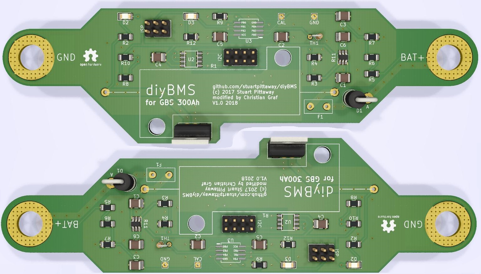
Since I am using bigger cells and will be charging them with up to 50A, I thought it would be better to beef up the circuit.
The things I changed:
R1 is planned to be a 0.5 Ohm 50W Resistor, this would put 8A through at max
The Fuse would be a Littlefuse RGEF800
The Mosfet is a Infineon IRL3716PBF
For D1 I thought of a OnSemi SB1245
The I2C gets connected from Board to Board with Ribbon cables, and since I need to flip every other Board the connector needs to be centered and the pinout should stay the same.
Its just a 2.2uF 1210 X7R ceramic capacitor ? there is no more info needed. If you scroll up there is a whole wishlist from Alie xpress you can just go through to check and then order, cheapest route!
Hi Chris, you won’t need to change the circuit - although I like what you have done!
The existing 2A load resistor would be fine for even large powerbank setups as its so rarely used!
The size and level of charge (current) you push into the cells doesn’t matter - the load resistor simply wastes energy to drop the voltage of the cell to equalise the voltage levels across series cells.
im waiting on my new version board there being ship will be 5 days till i can start adding all the parts as they come in the mail cost me $17.95 to get 30 made
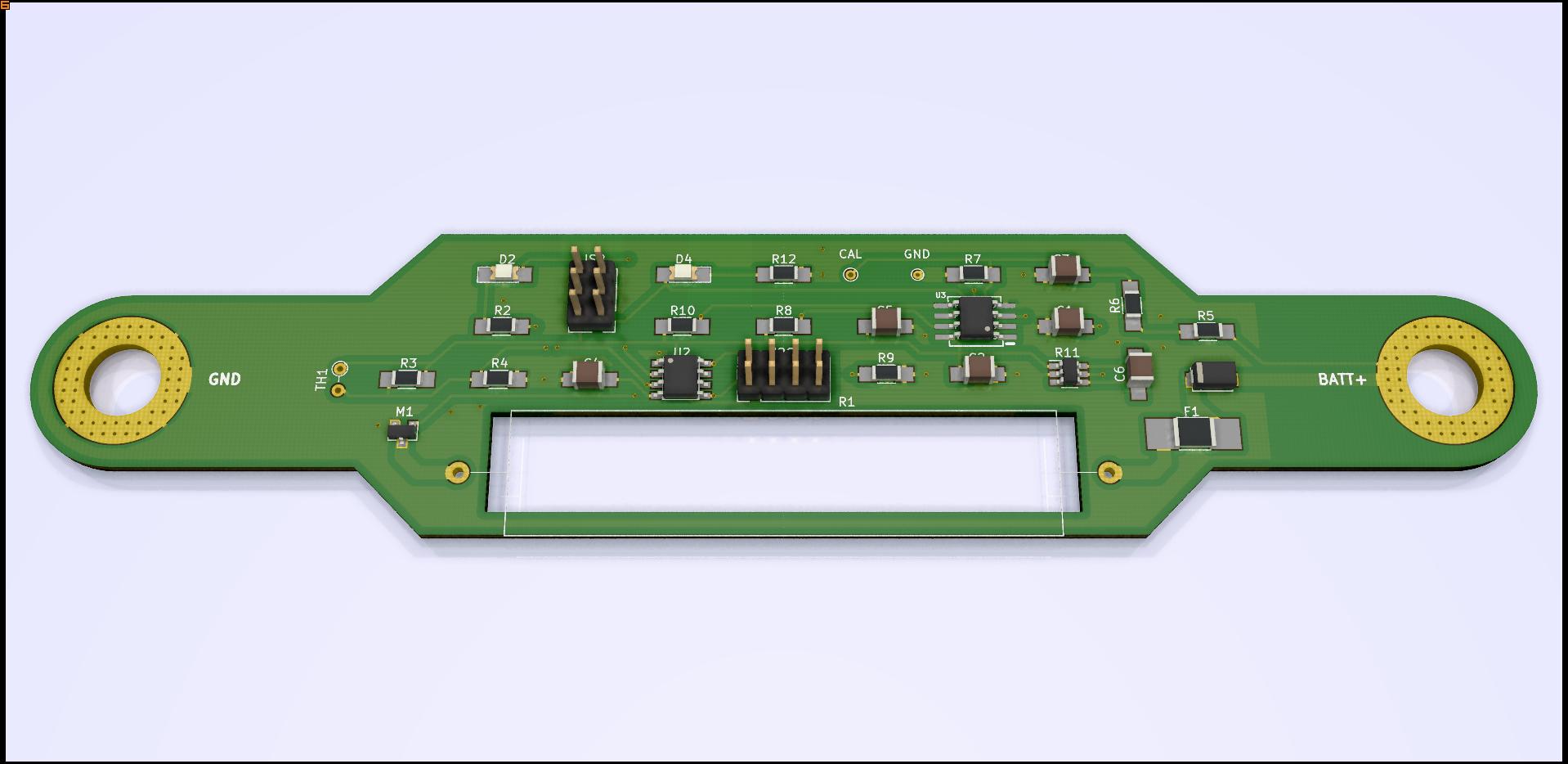
I remade the circuit using most of the components from stuarts V2.1.
The cutout for R1 is one size available and the silkscreen is the other. If i order the PCBs like this i can always trim away that small piece if i need the space.
What kind of cells do you use Vela_Nautica? It would be easy to change the spacing of the two M8 holes for a different cell. Or exchanging the Ground with a solder pad to solder on a cable.
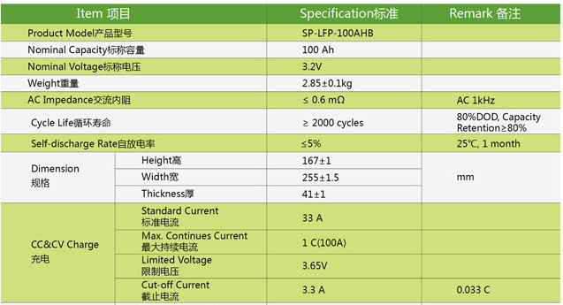
I plan to order these cells. company is AUK from china.
They dont let me place images in my post as new user…
LiFePo4 cells 3.2V100Ah
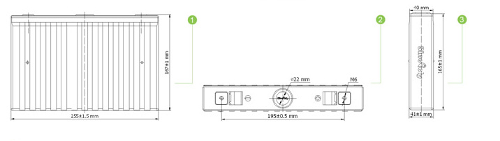
Size H 167 W 255 T41 mm
Standard current 0,3C Max Cur 1 C
pole disance is 195mm
other option is Winston cells but they are 40% more expensive.
We are an 54ft sailing Yacht and like to change our Lead Acid batteries to LiFePo.
The Batteries will be 6P8S.
A ship this size has a capacity of 24V600Ah.
we need 48 of these 3.2V100Ah cells.
Actually its 8S so we nead only 8 boards, my plan would be to extent one side bcs the spacing between the poles is wider than yours.
You wrote you beef up the board, I think thats fine just to be sure. We need to charge up to 175A with Alternator, standard charging is 120A because we need to charge with Generator and like to keep gentimes as short as possible.
I like th WiFi but would like to add some kind of serial UART as second connection to the ESP…
Where did you order your boards?
As i been doing some research about SMD capacitors there is leakage from capacitors my be is why the numbers are higher than the old style cylinder caps