For those who have sat through my YouTube video (and stayed awake!) I’ve released the smaller PCB design over to GITHUB - its in a separate branch for now.
A couple of the resistors have been changed to 4.7K simply to reduce the number of different components required - this will also make the LED not as bright as some people have reported issues with this.
I like smaller design much better. First of all boards will be cheaper. With panelizing hints from Colin you can get around 30 of them at about $12 dollars shipped. Also 0805 SMD is not much harder to hand solder compared to 1206 but the board is way more compact. Still have to try Stuart’s frying pan trick
thanks for that stuart
Just one last question is the file ready to download and also board requiremants like myself is the first time ordering a pcb make like copper weight, finish pcb thickness
found it all good orderd 30units now to find all the parts
so if i was to get 2 amp 8v Resettable fuse as 1.5 are hard to find ?
would it make much of a difference
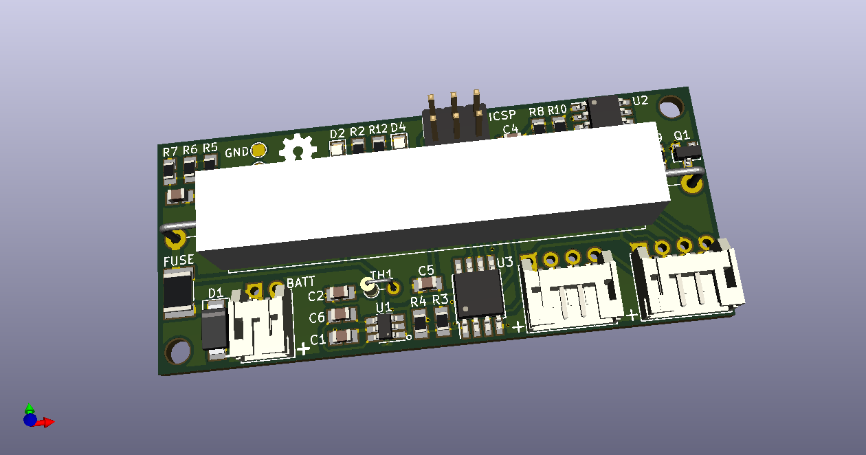
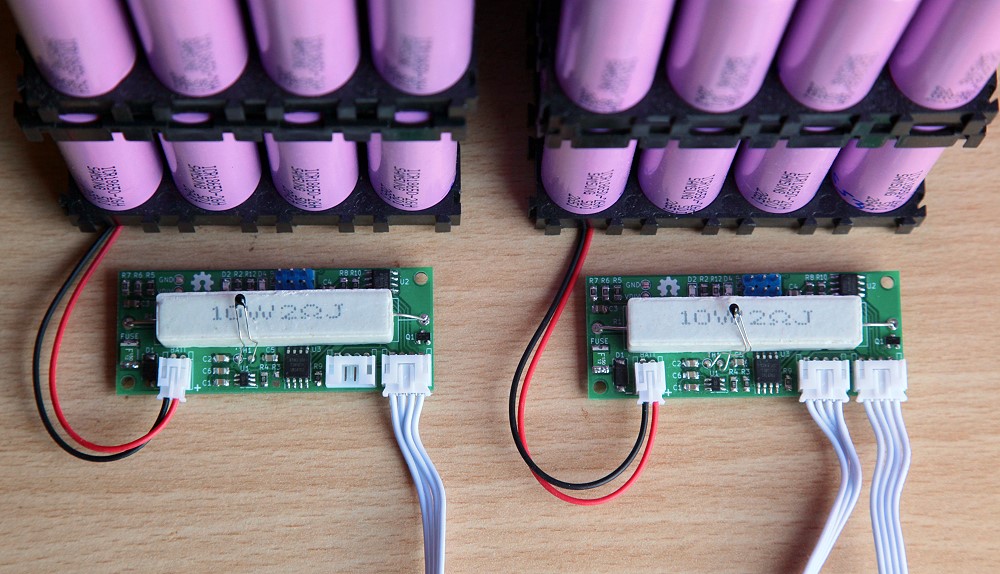
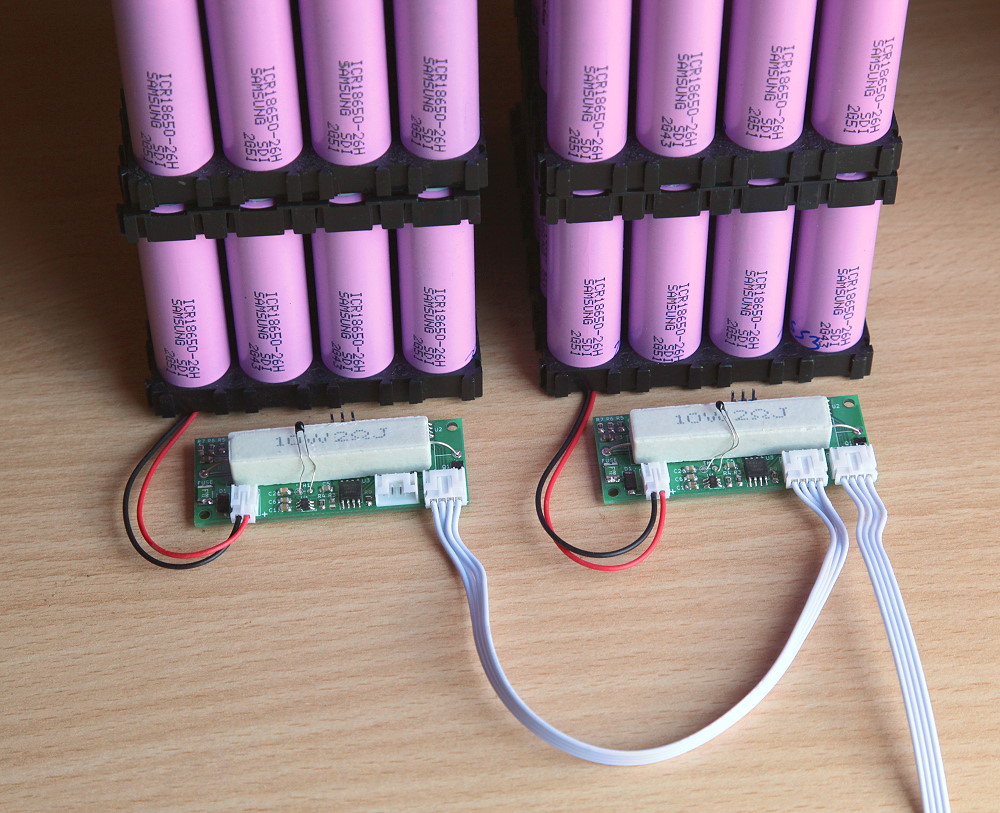
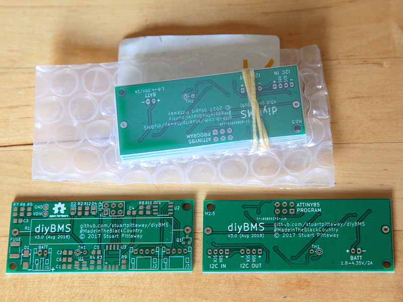
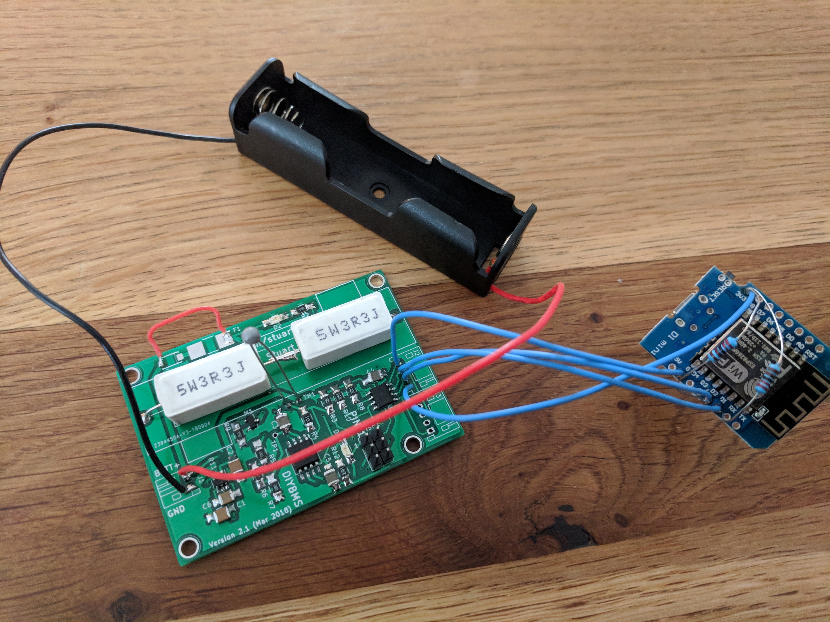
I thought people might like to see some photos of my v3 PCB “in action” ? Since v2.1 of Stuart’s diyBMS board (March 2018), this v3.0 is my complete redesign with the following improvements:
Smaller 0805-size SMD components instead of 1206-size (slightly cheaper and more readily available)
Far more documentation on the board silkscreen, including labelling all inputs/outputs, consistent orientation of components & labels for easier hand assembly, and marking pin 1 on all ICs
Thermistor labelled as fitting to front of board (for measuring power resistor) or back of board (for measuring battery pack)
BOM optimised with fewer components, and re-uses standard resistor values where possible
Supports a choice of data & power socket sizes: JST PH 2.0mm, JST XH 2.5mm, or generic DuPont 2.54mm
More reliable I2C communication with reversed ADUM I2C chip
2-pin power socket is now the standard way around (positive on right), so commercial red/black cables work without modification
Much smaller board, just over half the size of v2.1 at exactly 65x28mm
Via-stitched copper ground planes for better heat-dissipation
that does answer my question but more information on components more so like ohms. the more information the better would have to get parts in there local area.
as i look for some other the items like resisters under the info given but lacking key info like ohms and watts stuff like that. sorry if im a pain but not every one is a circuit guru
i’m aussie and info her is a major key to finding required part other wise our sale people look at u stupidly no former circuit degree
so i take it a 47R is 47ohms resister .1% threshhold
thanks stuart is mostle my source ebay, lcsc.com alibaba RSonline.com.au there valuse not everything is there may sites but all show diffrent valuse more than just ohms, or resistance. say is a part is out seeded out of stock need to look for next best closest value to items as in list in Pars build list
I handsoldered all my boards, its not hard or anything?? Whole mess with solder paste n stuff, i think i’m twice as fast with hand soldering… A good soldering iron/station does help though, i use a Metcal sp200. Its a gem.
Is it normal a cell module is pulling 12mA in normal operation? (no led or bypass on). thought it would be more in 3mA range, and actually was hoping for uA. Wonder if its worth implementing some sleep modes and lower reading intervals.