Just a reminder that this is a DIY product/solution so don’t use this for safety critical systems or in any situation where there could be a risk to life.
Hi stuart,
There is a lot of boats out there running on DIY projects only! or open source projects like openCPN doing all navigation with that.
but thanks we will not forget our safety.
sailors community likes their DIY because most times you know your stuff better if it brakes than to relay on comercial gear.
Oliver from velanautica.org sailing project for fun
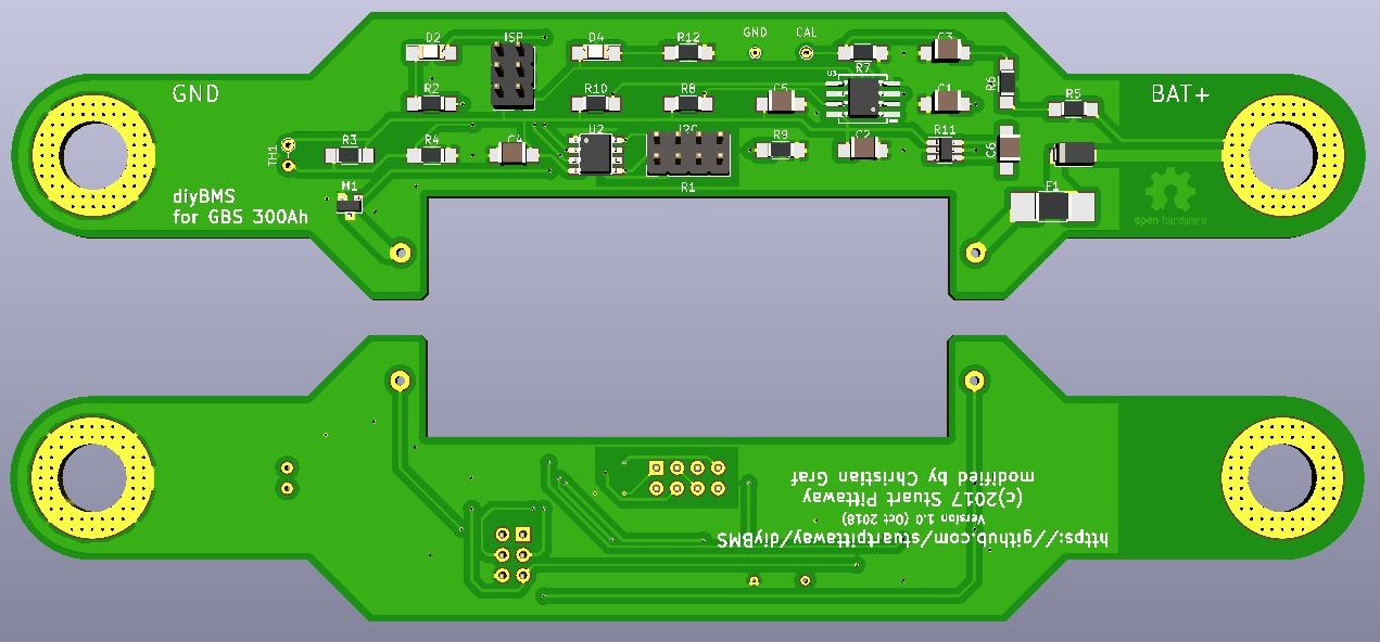
That does look quite good.
Where di you order you boards?
Why did you decide to use V2.1 was it? instead of V3?
Is V3 Version tested?
It sounds promising to me less parts and more standard parts more easy to get with V3?
You are from swiss right?
Did you get everything in swiss or germany?
I am quite new to this project and did now look around.
Did anybody try Farnell in GB as source?
so that was many questions lol 
Oliver from velanautica.org sailing project for fun
i got everything except the i2c isolator, diode and the JST connectors from de.farnell
edit: well and the load resistor wasn’t from farnell either.
I think i will order them at jlcpcb.com their prices are just too good.
V3 uses smaller components to get a smaller board size and better component availability.
Since i have the space between the two M8 screws anyway and this would be my first smd soldering, i decided to go with the “bigger” parts.
If i understood correctly, there is no difference in function between V2.1 and V3
I’m from switzerland, yes. I did not order any parts, but i think i end up with distrelec.ch, farnell, digikey as my partsources.
I am also quite new to this project, before I order anything I want to make sure the design I came up with fits and has no connection faults (but KiCAD is pretty much idiot-proof on the pcb-design and trace routing, you could screw up in the schematic though)
This morning I already saw three things I could change around and place better to get the traces optimized. And you also saw the first two attempts…
Greetings,
Chris
Correct, no difference - EXCEPT - the resistor divider uses 2 instead of 3 resistors (but the values remain near identical).
Why is i2C more reliable with that?
greetings Oliver from velanautica.org sailing for fun project
The chip has two i2c interfaces a “standards compliant” one and an “i2c compatible” one. The new circuit has the “standards compliant” facing out to the ESP module.
Hi everyone,
I have read every post in this forum and I didn’t find the answer. What is the longest string I can make? I am planning to build a 52S20P battery pack and I would like to know if it would support my project.
Thank you,
Adam.
A 200 volt pack?
Theoretically there isn’t really a limit - although I don’t think anyone has tried it with more than 14S so far. Some of the code may need altering to make it work with that many modules, but only minor changes.
The ADUM1250 is rated for 565Vpeak continuous, just keep the trace spacing and cable isolation in mind.
And dont touch any other trace or part if you plug in the I2C jumper cables…
Yes, it would be a 192V nominal pack. I have a Delta 6KVA ups and it needs a pack that big. You confirmed my theory, thank you. I am still in planning phase.
Thank you! Wise words, I keep in my mind.
how does that matter? it will only ever receive 3.3v on both sides anyways. one from the cell itself and one from the esp-controller side.
The ground from the cell is not on the same potential as the ground on the bus going from one cell module to another.
On the first cell the two grounds might be the same, but even that is not granted. This depends on where the voltage for the D1mini comes from.
The difference between the two grounds rises with every cell. On the first it might be 0V, then at the next 3,4V, then 6,8V and so on.
The term “Ground” on the cell module is not correct, it should be “Bat -” because you can ground any, but just one, point of a pack.
In bigger battery banks that are used in UPS systems it is normal to ground the middle of the pack. If we take the 52s pack with 192V as an example, this would mean that the minus pole of the first cell is at -96VDC and the plus pole of the last one is at +96VDC.
Hi,
what was the distance of your cell poles?
I my change to GBS 3.2V100Ah with distance of 68 mm and 4 screw connectors.
So I may need to modify the design.
salut Oliver
Its exactly 130mm, but i received the cells just today, so the last pcb design i uploaded to my dropbox is not yet correct.
But anyway, if you want to mount the PCB directly, another design is necessary.
That is a good point. It makes it much clearer, and probably safer, as it will go some way to dispelling the idea that it’s at a safe voltage, when it may be anything but that.
Agreed, I’ve opened a change on my design to include that in future releases