edit: Well, after reviewing everything I am having the same I2c issues everyone else has had. It appears there is a com issue but without a scope I dont know any other way to tell if it is sending or receiving anything. Any idea what to do or how to test the i2c without a scope
Stuart or Colin, I need a little Help I cant seem to get my boards provisioned. I am using ver 2.1 board and soldered everthing up properly. man it was hard to figure out where pin one for the voltage reg and i2c isolator went. But I got it figured out. I program them and the program with the boot loader fine and with the bms module firmware and they work fine. when I plug them in the green light comes on then goes out for a second then lights back up but when I select provisioning the blue light on the wemos lights up but the bms doesnt do anything and I get no return for the provision. Was wondering if youhave seen this issue. Also D1 is my scl and D2 is my sda. I even tried swapping them. The only component that was used that is different that what you suggested in BOM is I used attiny 85-20su. But from what I have read that shouldnt matter right. But what do I know this kind of electronics thing (I used to hardwired radio and PC electronic builds) is new to me. Any help would be appreciated.
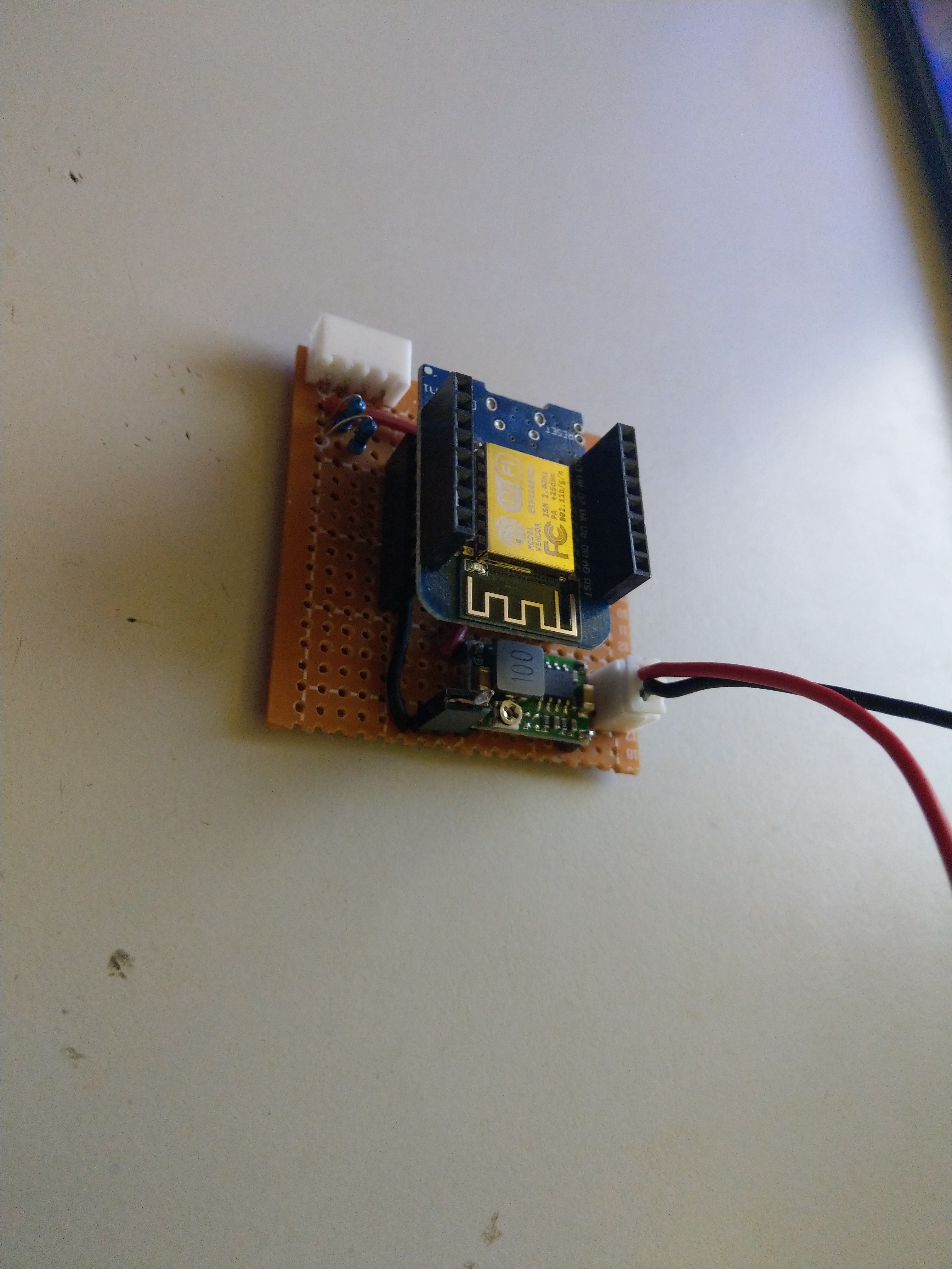
After some hours and a blown up usb controller on the Wemos D1 (the one in the picture) i finally have a little board to connect the modules to!
For some reason the regulators or the usb chip on the wemos fried itself. When i power it with 3.3v it will still boot up and i can acces it through a browser so i’ll just keep it like this till i need to reflash it!
Didn’t manage to provision my first module yet, for some reason he can’t find it. Also tried a i2c scanner on a Arduino Uno connected to the module but that also didn’t yield a i2c device found (or is this not possible with the code on the attiny85?).
Hello again
Still suffering I2C comm (non-comms) between wemos and module. I have done more testing. I am posting the results that may give the more experienced a clue to my woes.
Step 1:
I can upload and run a Blink sketch through the ATTiny on the module, which will then pass through the ADUM and cause an LED to blink. This makes me think that the ATTiny/ADUM relationship is working.
Step 2:
I have 2 very simple I2C sketches (master | slave). I put the Master Sketch on the wemos. I put the slave sketch on the ATTiny85 SMD on the module.
I can achieve Comms if I hook-up the wemos directly to the 6-pin (programmer connections using 4-pins) that go directly to the ATTiny.
When I try to move the connectors from the 6-pin programmer to the 4-pin connector on the module which go through the ADUM, I get NO-Comms.
The only thing I can come up with is that their is not a common ground, but when I try to establish one, that does not make it work.
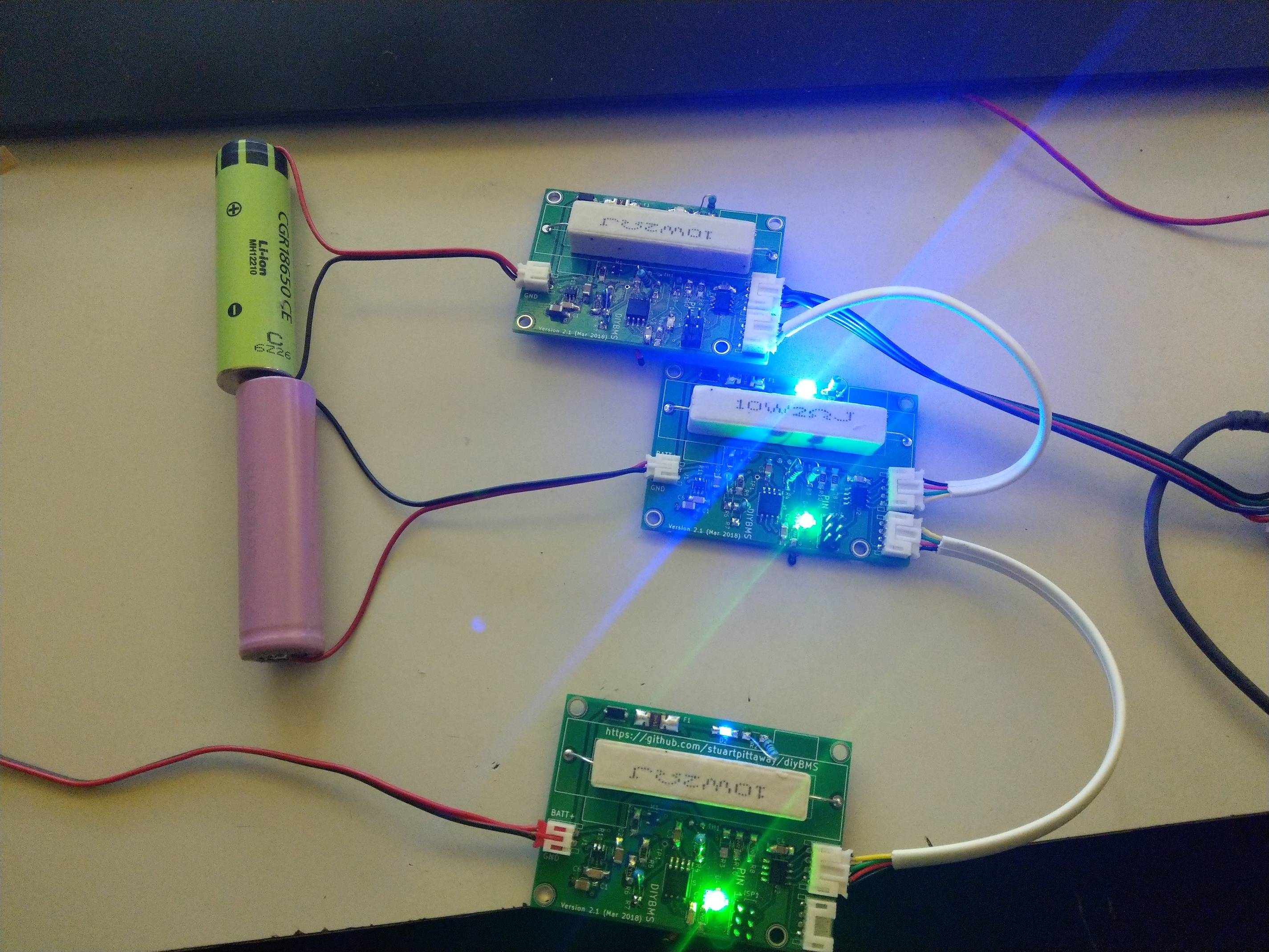
I finally got my set working, two showed 0v or 65v so i figured provisioning 3 modules. It worked instantly!!
Regarding your coms, do you have a arduino Uno?? I used one to program them all.
What i did, because i’m kinda a noob but learning fast on this one!
1: configure the sketch on the uno as “arduino ISP” its a standard script inside IDE.
2: configure the right values and settings for the attiny85 then disconnect the uno.
3: wire the isp connector up to the uno and plug it back in.
4: burn bootloader to attiny85
5: upload sketch
Then it is absolutely important to plug 1 module to the wemos/nodemcu and provision it. Don’t unplug anything!!! everytime i did i had to flush eeprom and do basically step 3-5 again!!!
When the green led on the module is blinking while uploading your script, atleast the attiny85 is good!
After you hook it up to a cell (i use 1 for testing) the green led lights up, for a second, turns off and after a second or 2-3 it will light up and stay like that. If its in that state do the provisioning.
1: Which steel cabinet are you using for mounting your batteries?
2: And is the software at the point where it can be used for balancing? Read something about that the code is there but not yet functional?
1: configure the sketch on the uno as “arduino ISP” its a standard script inside IDE.
2: configure the right values and settings for the attiny85 then disconnect the uno.
3: wire the isp connector up to the uno and plug it back in.
4: burn bootloader to attiny85
5: upload sketch
Thanks for your post of steps. I was using a USBasp for programming the ATTiny. I am now using my UNO.
I also purchased a reworking station and made a new board using hot air.
I have had further success. My I2C comms is working. Running the Controller from my wemos, It connects to the module, but then fails. See below for Serial Monitor output:
runProvisioning
Found 24
connection failed
Any obvious things to start checking?
Thanks for all those who have been helping me Colin, Stuart, Joey…
Hi,
I ordered pcb and some parts , but i would ask:
Why not use specialized IC like LTC6811 ?
Ok is quite expensive chip but you can build more compact solution and is simple to interface with arduino.
Great!! you have progress that is all we need right? Haha.
What i found is that with one module it can give errors. If you can try to make 3 modules useable, you can leave the load resistor out of it for testing, and then it shouldn’t give any errors anymore!
The ‘connection failed’ was due to I had the wemos configured with InfluxDB in the ‘On’ position with no connectable information. I have changed the configuration to ‘Off’ for InfluxDB.
In the above scenario; no module stats ever popped up.
Colin; my Resistors are 1K ohms.
But now my wemos is back to not recognizing any module. I have reset the bootloader on the ATTiny, I have reloaded the script on the ATTiny. I have reloaded the script on the wemos. Still, I am back to :’ Provision 2 no module’
Either running the Test Controller or the Controller sketches.
Joey. I do just have one module without a load resistor. Should I try attaching a load resistor or making more modules?
I think you should be fine without the load resistor, do you have the thermistor connected out of interest? I know Adam welch had issues when he didn’t have it connected and was attempting to provision
Ah i know this one!! you have to flush the eeprom!! I did it with a basic eeprom sketch that wrote all entry’s to 255 (its 0 by default). But don’t quote me on the number, just google flush eeprom attiny85!
You guys seem to run into unusual problems that I’ve never seen/had. The ATTINY chips have been rock solid for me when programming and “playing” - never needed to burn the fuses more than once and never had issues with the EEPROM settings etc !
I know some of the unusual problems i had were purely down to myself and happy to admit them if it helps others. Once everything was done as per the design it’s been working great and provisioning fine.
I had an issue with burning up a track on a board which was down to reversing VCC and GND on the input, how can you be so stupid you ask? Well, I foolishly grabbed a connection lead from the parts box and it turned out I had leads from two different suppliers and one had the colours one way and the other had it reversed and I didn’t check…
The second major issue I had or seemed major was the fuses, I hadn’t set them so the speed of ATtiny was incorrect. I was proud of myself that I found a work around and masked the issue successfully by altering the clock stretch, but that was a fudge and when I set the fuses and speed correctly it worked great.
The third thing was not an error as such but being lazy, with one module I found pullup’s weren’t required and was also initially convinced they were already on a Wemos D1 mini, but after trying to provision multiple units, they are not on a Wemos so needed to be added. Currently running 1k.
The last was not a mistake as such, but did take me a little while to track down, and that was interference from my inverter. A screened power output cable to connect to the mains solved that.
Well Stuart, the eeprom thing only came into my sight because once a module was found and the esp lost power. It wouldn’t see the module anymore! Only flushing eeprom helped. And i had that on 5 boards now, i guess its not normal?