Hey Stuart;
I do have a multimeter and have been doing continuity checks on the ADUM and the Attiny85. I have also been resoldering the pin/pin pads also.
I do not know how to check for the actual I2C comms. I have added a line to the test_controller.io to show the result of the wire.begintransmission. It returns code ‘2’, meaning no-comms. I did switch the SDA/SCL pins in the code. Then I got an error code of ‘4’ (Unknown error). But it does mean some type of comms happened.
I am going to resolder the WEMOS side of the ADUM pins this evening. They are close to the plastic plug on the module so they are hard to get to without doing damage.
Hey Stuart;
Results from the led and resistor test on I2C comms:
WEMOS - controller_test.io - LED Light does not show a flicker on the SDA or SCL line when serial monitor commands are sent. LEDs are dimly lit.
WEMOS - Example_I2C.io - LED flickers on the SDA line when transmission sent every 2 seconds.
Voltage Tracking:
Wemos -Example_I2C.io - 3.3 volts on SCL, drops to between 1.5V and 2.7 volts when transmission sent every 2 seconds.
Well i purchased the reg10s from alixpress because they were a lot cheaper than buying them from mouser for $1.20 each. They seem to be fakes because on some I am getting 3.4v instead of 3.3v where as all the reg10s purchased from mouser output 3.3v. Also one was doa and other started rising from 3.4v to 3.8v.
Hey Colin;
No luck. No I2C comms working.
I have simplified my hardware and software. I went back to just getting I2C comms to work between and arduino and a ATTiny85 on a bread board. I got that working.
I then transfered the arduino code to my wemos and got the wemos communicating with the ATTiny on the breadboard.
I have copied the same ATTiny85 code from my breadboard chip to my ATTiny85 SMD. I have not done that test yet.
I am struggling but refuse to give up.
Bob
I cannot write the bootloader to the module attiny any more. I get the ‘no signature error’.
Could this be something to do with the USBasp I am using. I get the message:
avrdude: set SCK frequency to 187500 Hz
avrdude: warning: cannot set sck period. please check for usbasp firmware update.
I have read to ignore the firmware update message. Does the SCK frequency mean something?
I was hoping I could write a basic I2C comms sketch to the module attiny, but could not get that to work. But as stated above, I could not get the bootloader to work (command line or from arduino IDE). I was wanting to just set the 8MHZ clock speed.
To set the boot loader all you have to do is go into Arduino settings (select ATTINY, 8Mhz internal) and click “Burn Bootloader” from the menu.
I suspect you may have accidentally set the clock to external - in which case its a pain to reset and you would need to temporarily connect an 8Mhz crystal to the chip and re-program (I’ve made this mistake a couple of times!!)
I’m surprised you are getting so many problems - unless you have multiple faulty components ?
I’m surprised you are getting so many problems - unless you have multiple faulty components ?
actually, I am surprised too. There seems to always be that one guy who just can’t get it. I seem to be that guy on this project.
I am running out of ideas.
Is my thinking sound, that I should be able to ping the module with a basic I2C sketch using Arduino/wemos…
Or is there something special in the code of the module or controller?
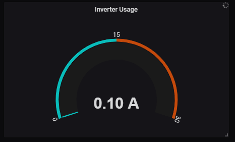
For anyone interested i have updated the controller code so that it can now monitor inverter usage by hooking up a ACS712 sensor to pin A0 and then you place the ACS712 inline with the negative connection from the battery to inverter. You can configure in the code if your using a 5A/20A or 30A ACS712, you can also change the pin if you have a different board. At the moment i am pushing it to grafana as usage in amps however i may change that to watts which i think may be more useful.
The beauty of grafana is that you can display it however you want. you could technically calculate it in grafana as you know the pack voltage, but I was trying to think of what was actually most useful and I tend to look at the watts rather than amps, so may change it to that. Thanks for the feedback though, really appreciated
Thanks! I’m currently trying to write the modules through the Arduino IDE, but i’m getting walled with the USI_TWI section, there is something wrong in the library but i can’t find out what
In file included from Documents\Arduino\libraries\USIWire-master\src\USI_TWI_Master/USI_TWI_Master.h:76:0,
I am trying to compile and flash the DIYBMS module code to the attiny85. When i try and compile the USI test slave or master code, same error. When i change it to a Arduino Uno it works just fine.
It was late so i didn’t try any further but it must be something small right ? !
EDIT:
I messed around with it a bit and followed your video on yt Colin! (very helpfull). I can get everything flashed except the BMS code !! it keeps giving above message. Am i using a outdated library ?
Also with LTO set to enabled i can’t flash anything, when i disable it blink for example works just fine!
EDIT2:
Problem solved, installed a different TinyWire library and it compiles right away!