Hey Guys;
Took awhile to get all the parts in. I have put 2 boards together. I have flashed the attiny. When I add power to the modules I get a Green light for about 5 seconds. It goes dark for about 5 seconds. Then it comes back on and stays on.
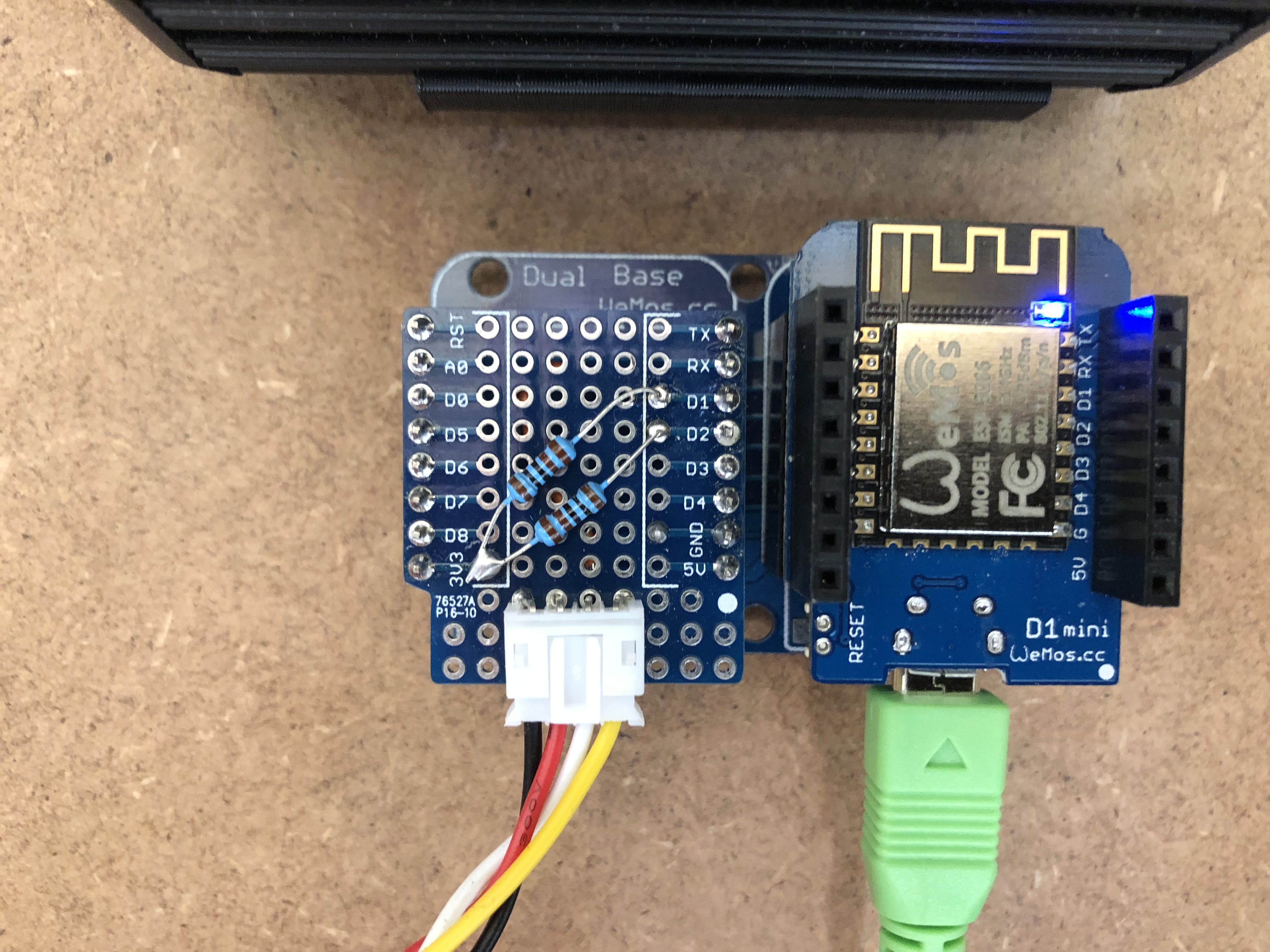
I am using a wemos d1 mini as the module controller. I have flashed with a USBasp. I used the settings described a the top of the Arduino code for the wemos. The wemos took the code I am able to connect through wifi.
My problem is that the controller does not recognize any modules.
I have made plenty of mistakes along the way:
Wired up the Module2Controller backwards.
Had the wrong IC on the module 1201ARZ instead of 1250ARZ.
Any ideas on what could be wrong?
I think I have read that when a connection to module is made that you get a Green Blinking light. I have not had this.
Also, I am curious about the attiny Reset mentioned by Beardman.
The solid green light indicates that it’s in a factory reset state and has not been provisioned, which is a positive step. The flashing is that it’s in a panic state and can’t communicate with the controller.
When you say you’ve flashed it using the settings, have you also set the fuses/speed etc? You do this by setting everything as needed and then choosing burn bootloader, it’s the last option in the tools menu. You need to do this as the speed on the ATTiny’s is set at 1MHz by default, uploading the code won’t set the speed. Once you’ve done this you can then go into the web interface and provision the module.
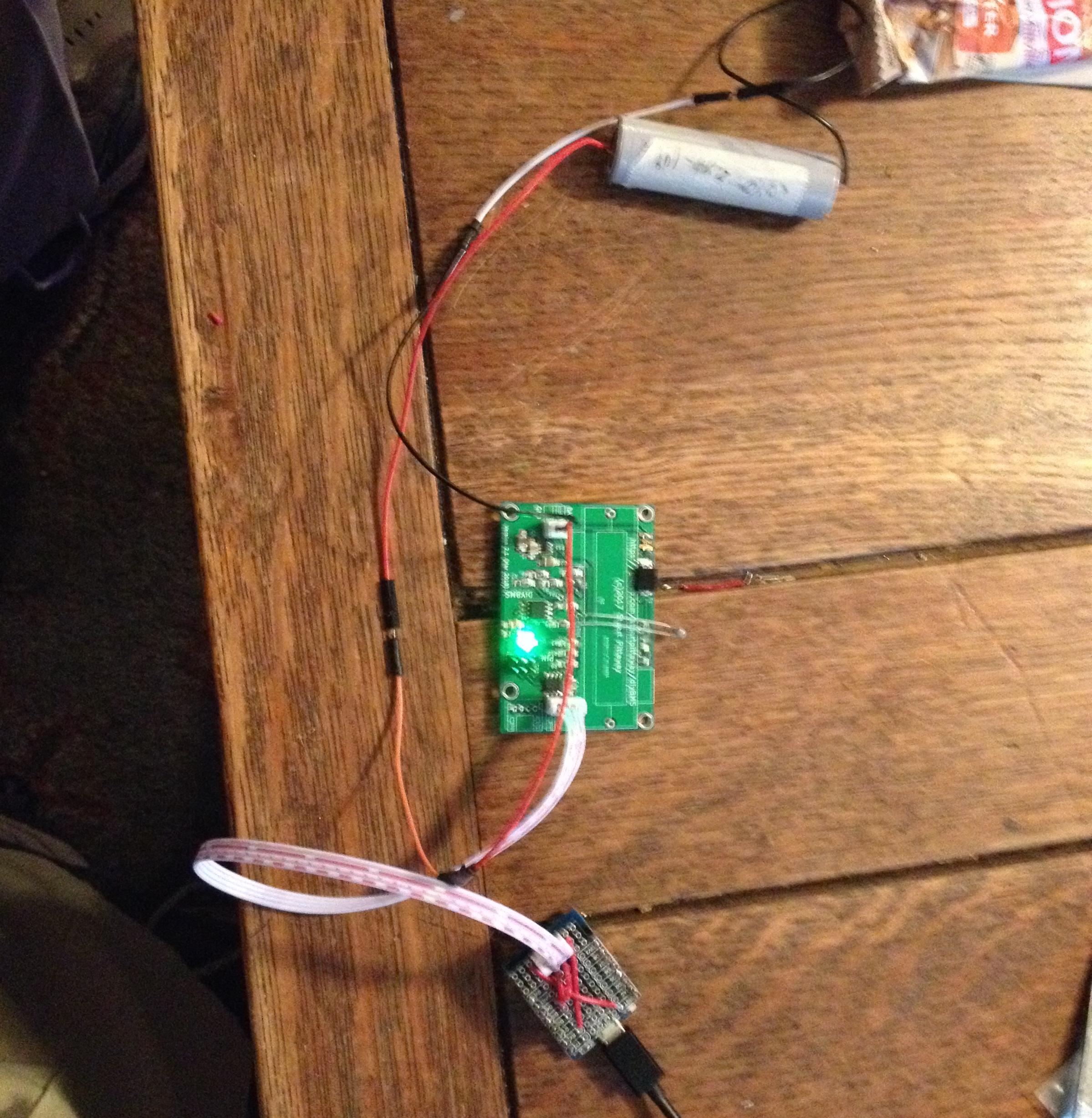
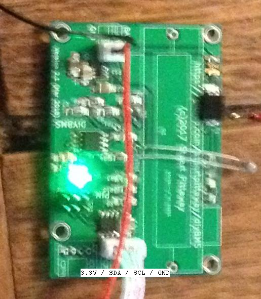
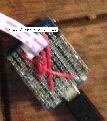
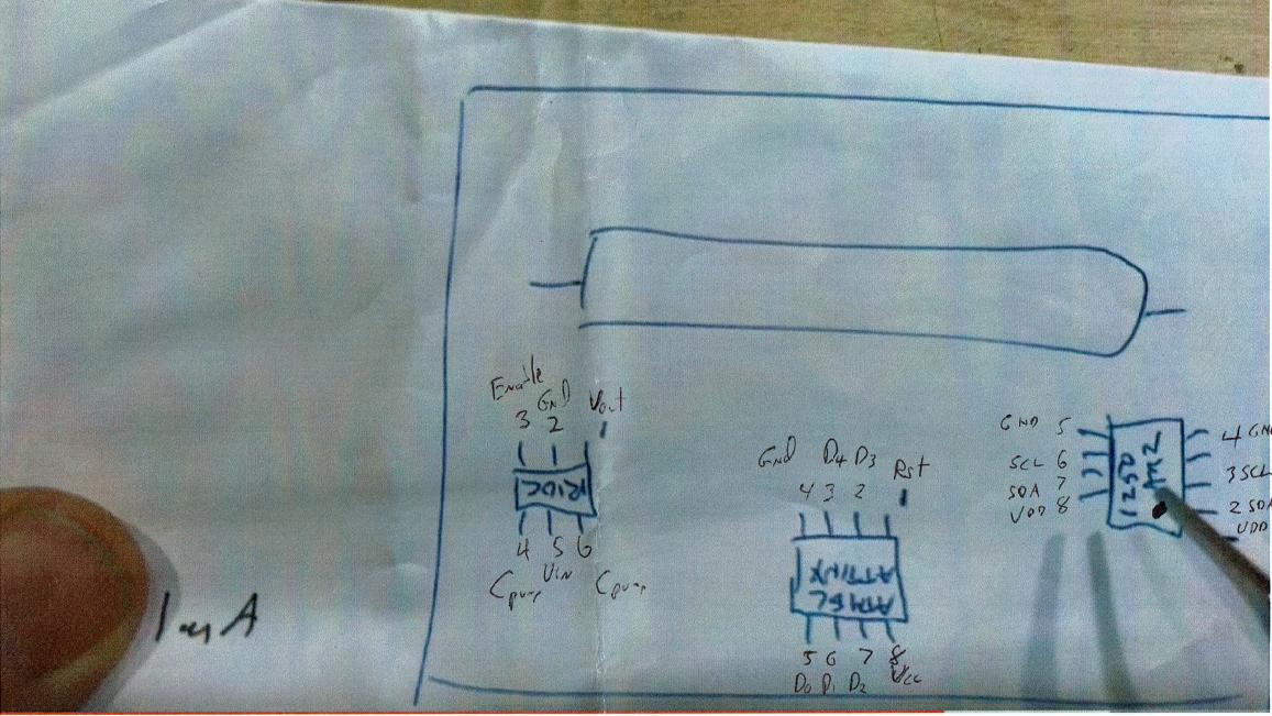
Just for clarification, attached are some photos of what my module and controller looks like. I have added pin positions. In the controller picture, I do not have pull-up resistors, this is a shield I made without them (some information says that the wemos d1 mini has built in pull-up resisitors.
Okay, disconnect the module from the i2c cable and then test with a multimeter between ground and the clock and data lines - both should be 5V if not, you need pull up resistors!
I’d recommend using the controller test program which stuart wrote. use that and look at the serial output, when you do an X and search does it show any modules and are you able to provision it? if you can if you do an R for reading (i think) does it list 4 consistent values?
Re the cables have you made sure that it’s linking to the correct pins so when you look at the two plugs they are identical.
Re my earlier comment about speeds and burning the bootloader, did you do that step?
I spent yesterday building a new module (being as careful as possible). It may be just me, but whether I bake a module on a hot plate or solder each component, I have to do a good bit of ‘fixing’ of solder joints throuh my multimeter using continuity testing and voltage checks (I am learning alot about electronics).
I have been using the controller test program for troubleshooting.
No modules answer on ‘P’ cmd. No results on ‘X’ scan.
I have checked, and re-checked the alignment of the pins from wemos to module (gnd2gnd, scl2scl,sda2sda,vcc2vcc).
I have done the bootloader for the module. I have noticed that the green light now activates quicker when power applied.
I have NOT done the avrdude speed settings. I have been a little nervous about doing the command line switches. I guess I need to move forward with this.
I have removed the USBasp programmer from the attiny85 process. I am now using the arduino with an attiny shield.
Without the speed setting it won’t work. You can set the speeds by burning bootloader as I mentioned earlier in the thread. The code is designed for an 8mhz chip and your running it in a 1 MHz chip so all the timings are off.
You can mask this by modifying the clock stretch as I’d mentioned above also but it is purely masking the problem
If you look further back in the thread regarding clock strech, try those changes out of interest. When i had issues with the clock speed i was able to change that setting and i was able to mask the issue somewhat for the initial comms at least. it’s also on my youtube channel. Colin Hickey - YouTube
I tried setting clock stretch to 1500 and 4500, still nothing. I am running the controller test.io I have tried on two different Wemos D1 minis. And a couple of different modules (my module building skills are not the best).
@Bob_Brundage do you have a multimeter with a logic probe function on it, if you do try probing the i2c data pins on the module - do you get a signal/data flowing?
Try both sides of the ADUM chip to ensure thats working okay?