DIY Lithium Battery Balancer and monitoring (BMS)

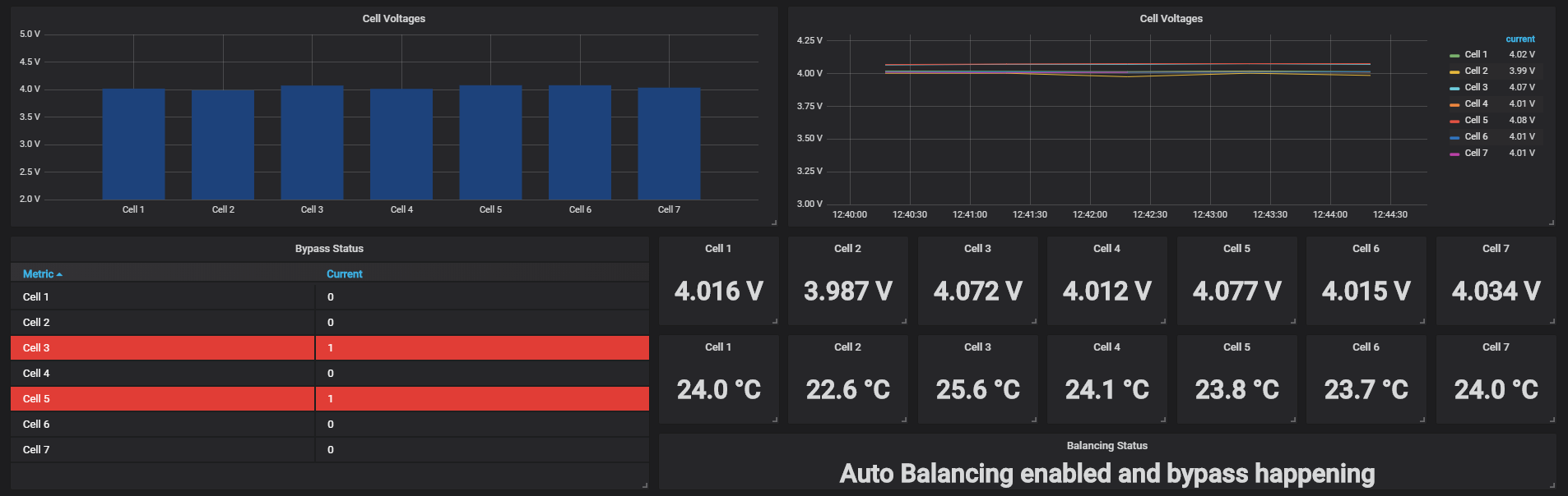
As things have settled down on my setup now I’ve been adding a few more features today. I have added an additional column to display the current bypass status in the modules screen so you can see at a glance in the web interface. I have also added a button on the main screen so you can stop a manual average balance which has been started.

I have also added an auto balancing option and you can set a minimum voltage so that it will work out the average and only start an average balance if it is above the value you have set to ensure that it’s not trying to balance for ever and running your pack down. I have also added a maximum cell voltage setting so that you can specify that you never want your cells above say for example 4.1v and once a cell reaches this voltage it will enable bypass on that cell and try to bring it down to the value you’ve set. While it’s doing this top level voltage protection it will not try and balance.

It’s still a work in progress but i hope this might be useful to people, will pop a video up tomorrow showing it.

I have given it another try… but again I run into the same issue…

I have reset the EEPROM, reflashed the Cell Module, it now lights up constant…
I do a provision (with only this one board connected)
This is from the serial port of the controller:

DIY BMS Controller Startup
A7EFFFEF
A7EFFFEF
Settings loaded from EEPROM
Connect to WIFI AP
WIFI Connecting663. Connected IP:10.10.10.197
Management Redirect Ready
runProvisioning
Found 24

I am now able to see the module, and its voltage and temperature… works just fine…
I then press the reset button on the controller…

DIY BMS Controller Startup
A7EFFFEF
A7EFFFEF
Settings loaded from EEPROM
Connect to WIFI AP
WIFI Connecting666663. Connected IP:10.10.10.197
Management Redirect Ready
runProvisioning

After awhile the Cell Module starts to flash its LED… “Panic Mode”… I am unable to see the module on the controller anymore…

I have tried just about anything… I have a 15cm cable between the controller and the Cell module… I use 10K pull-ups on both the data lines… I have tried to twist the data lines…

My controller is a D1 mini, I’m using D1 as SCL and D2 as SDA just as described in Adam Welch’s video here: diyBMS - Programming a module with an Arduino - 12v Solar Shed - YouTube

The cable between the controller and the cell module is straight through, and I guess it would not work at all if SCL and SDA were swapped, as well as if positive and negative were swapped?

Last ting to try is always the one which fixes it :wink: I grabbed a new D1 mini module… and yep, it works now…
Or… lets just say… it makes a different if you select “D1 mini” as the board or if you select “NodeMCU”… and yes, I can clearly see that it is mentioned in the code, just thought I knew better, and that it didn’t make any difference… well lesson learned :slight_smile:

Onwards and upwards! Lets solder some mode boards :wink:

So your using a D1 mini but selecting NodeMCU as the controller type fixed your issue?

Correct :slight_smile: The LED on the D1 Mini is also blinking now… it didn’t when I used D1 mini as the board… yet everything else seems to work… (but not really as described) :slight_smile:

That’s really weird, i’m still getting lots of interference on my wemos so i might try using the NodeMCU i have as a replacement as it might be less susceptible. Apart from that if i keep my inverter powered off it’s working pretty well and balancing nicely.

Yes, this was a strange issue… as described before, everything was working great, until I reset the controller… then it was unable to discover the cell modules…
Also the blue LED on the controller was not blinking when flashed with the “D1 Mini” board setting, that was actually what I found strange… first I thought the controller board was faulty, but I then tried to reflash it with the “NodeMCU 1.0” board, and I now have two working controller modules with which I can play :slight_smile:
I suspect that Stuart has been using this setting all along, as it is actually pointed out at the top of his code :slight_smile:
"Arduino settings: NodeMCU 1.0 (ESP-8266-12E module), Flash 4M (3MSPIFF), CPU 80MHZ "
Maybe the I2C is a bit different with the other board… who knows…

He’s using a nodeMCU board so he’s using that setting. I’m using a wemos and using the wemos setting it works ok, i wonder if your board definitions have become corrupt somehow.

10K is way too high - 1K would be better

In case you didn’t realise, that “24” is the i2c device number of the cell module

Noted :slight_smile: It seems to work alright with 10K now, but I will swap it to 1K later on.

Just to update folks adding a few more features, it’s coming along nicely.

2 Likes

Hello to all the smart people working on this project.

I have a question. Would this system work on a Chevy Volt battery? I have a 2018 Chevy Volt battery and have it wired into a 14s6p setup. 14 cells in each bank wired in parallel with 6 other banks.
System voltage if i charge to 4,2 volts per cell (which I don’t) is 58.8 volts. I charge to 4.0 volts per cell.
I am a industrial electrician by trade and not a electronics person at all.
I am looking for a BMS system for the battery and came across this page.
Thanks for any help.
Thanks
Jeff

1 Like

Hi Jeff, It’s @stuart’s baby but I’ve done work on the controller code. I think it should work pretty well for our needs as it will support 14 modules. I have only seen a max of 7 used in the wild though. I have a 7s96p setup which is working well. Automatic balancing is working well so far although it’s early days.

Ideally you want to pair it with a charge controller where you can limit the charge voltage so in your case around 56v and any slight inbalances can be handled by the BMS. Depending on your choice of power resistor you’re not going to be able to burn more than say 10w max per module but if you’re limiting the voltage in your charge controller then you should still be good.

Hello Colin

Thanks for the reply. I made a mistake in my information. I have only 6 banks of 14 cells. So a total of 84 Cells to monitor. Each cell in the VOLT battery rated at 25.2 A-hr as far as i have been able to find.
I have to charge controllers that charge the battery up currently. They are OUTBACK FM60 charge controllers. I have them programmed to charge to 56 volts and then they throttle back on the current going into the battery. They still are active and on maintaining the 56 volts as the loads vary in the house. When this happens the charge controllers will increase the wattage pulled from the panels to make up for the load that the inverters are putting on the battery, to the limit of the 2.6 kws in panels that I have. I can charge the battery via the inverters as well. Max each inverter can put out is 45 amp DC at 56 Volt.
So my question is (since I am idiot when it comes to electronics) where can I get these boards? I take it from reading that you can buy them from China? I also take it not populated?
I am just trying to figure out whats cheaper, pay somebody to populate them? Or try my self? Problem is my skills at soldering are related to replacing relays and larger parts on inverters that we fix. Would it be cheaper to go with a Batrium set up? They make a nice unit, but the longmon board is 20+ Canadian per board, and i would need 84 of them. They offer a starter kit for some 700 plus dollars and that includes current shunt, 14 long board and the watchmon4 unit.
Just want to pick the smart peoples brains out there eh…
Thanks for any and all help and or comments.

Jeff

Hi Jeff, If you have 6 cells in parallel then you should only require one BMS for those 6 cells as a whole as they will all be the same voltage when in parallel. That would also apply to the longmon setup in that you shouldn’t needed more than 14 rather than the 84 you mention as the system looks at each bank as one cell if they are in parallel.

If your not confident in soldering and coding in all honesty i’d say the batrium may be a better solution as it’s a commercial solution which you can get support on if required and will be a fare easier install process.

Col

Hi Stuart, I wonder if you have seen any of the changes i have made regarding auto balancing and balancing above a certain voltage as well as a configurable max safe voltage per cell so a top balance of sorts. I’ve also implemented a status in the web interface to show if a module is in bypass or not. Cancel average balance/reboot controller etc.

Would be great to get your opinion and i could look into some pull requests if you were interested in merging some things in.

Yes I’ve been following your changes - all look good, you have been working hard!

Only suggestion I would make is to move the balancing logic into the module ATTINY code - it would be preferable if these modules were autonomous to limit the voltage should the primary controller not be working or fail for some reason.

I had been discussing something similar with a friend who’s using yours setup in Florida as we both actually though the max cut off was already in the module code but after i looked you only allow the bypass voltage to be set within a safe range which makes sense. I was thinking a hybrid approach may work, i like the idea of the balancing code and logic being in the controller however the max safe voltage which is set in the interface could be passed to the modules and then if they lose connectivity while they will not balance per se they will go into bypass as soon as they reach the max voltage you’ve set even if they can not contact the controller. That should be possible without too much of a re-write.

1 Like

Nope that wont work. I have 14 cells in series which make up a 58 volt pack.
I then have the 6 packs in parallel. So total of 84 cells to monitor.
The Chevy Volt Battery is not easy to work with as the cell interconnections are welded together.
The total cells in the battery is 192 cells but they have 2 cells in parallel in the pouch. They then call that one cell but its really 2. Confusing eh. So I have 12 cells not being used in my battery. I guess I can call them spares eh. Total battery capacity 18.5 KWH at 365 VOLTS DC. Chevy used about 10 Kwh out of the battery before the Gasoline engine would start up.
I will continue to monitor the thread and see how you are doing.
I will also research the Batrium system as well.

Ah i get you so kind of 14s1p6p. With the DIY BMS as it is you would need 6 controllers and 14 modules per controller.