Contribution: Samsung ASHP NASA link <-> MQTT bridge (Home Assistant)

This is a very good idea but problem with this solution is that you will not know the current tank temperature. So if you disable it because e.g. the space heating is disabled over night and you want prevent AF or anti-seize cycles then you have no idea about tank temperature and if it should be reheated or not so it’s a bit inconvenient. I could install another heat sensor which would send data to HA but it’s a bit overcomplicated.

Seems still automation with use of relay is the best one to prevent stealing the heat but relies on shelly integration and HA operative. I guess this could be solved only by Samsung if they would simply introduce a new field setting where we can choose which circuit is used for AF cycles in case DHW tank is connected.

Good news, I just tested disabling DHW via fsv3011 and the rank temp is still returned by the mim controller board :slight_smile:

Cheers

EDIT: after few hours, the value of the tank temp still move, despite the fact it’s a disabled feature. So I presume, the DHW feature enablement is orthogonal to the temp…

Hi @toadhall,

I had a quick look at your NASA traffic disassembly – your code to produce that output must be VERY impressive.

Out of academic interest, I compared your #2021 change request instruction (setting it to 46degC) with the one that SNET-Pro2 produces. Here is yours, as I interpret your log:

And here is SNET’s:

There are some obvious differences:

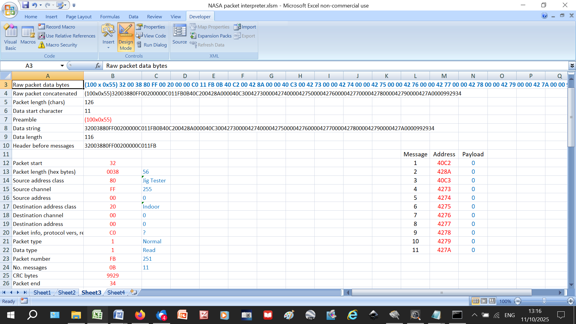
· Your preamble is short (FD FD FD FD F1) whereas SNET sends (exactly) 100 0x55 bytes. This seems to be the standard SNET output protocol. For example, when I first switch on my proxy it transmits dozens of packets like this:

(100 x 0x55) 32 00 38 80 FF 00 20 00 00 C0 11 FB 0B 40 C2 00 42 8A 00 00 40 C3 00 42 73 00 00 42 74 00 00 42 75 00 00 42 76 00 00 42 77 00 00 42 78 00 00 42 79 00 00 42 7A 00 00 99 29 34

A glance at the payloads suggests that it is zeroing all its registers, presumably part of its setup process:

· SNET declares itself to be a “JigTester”, whereas your code is “Wi-fi Kit”, and the Source and Destination Channels and Addresses differ

· Your Data Type is Request, whereas SNET’s is Write.

Yet they both produce the same result – #2021 gets changed to 46degC.

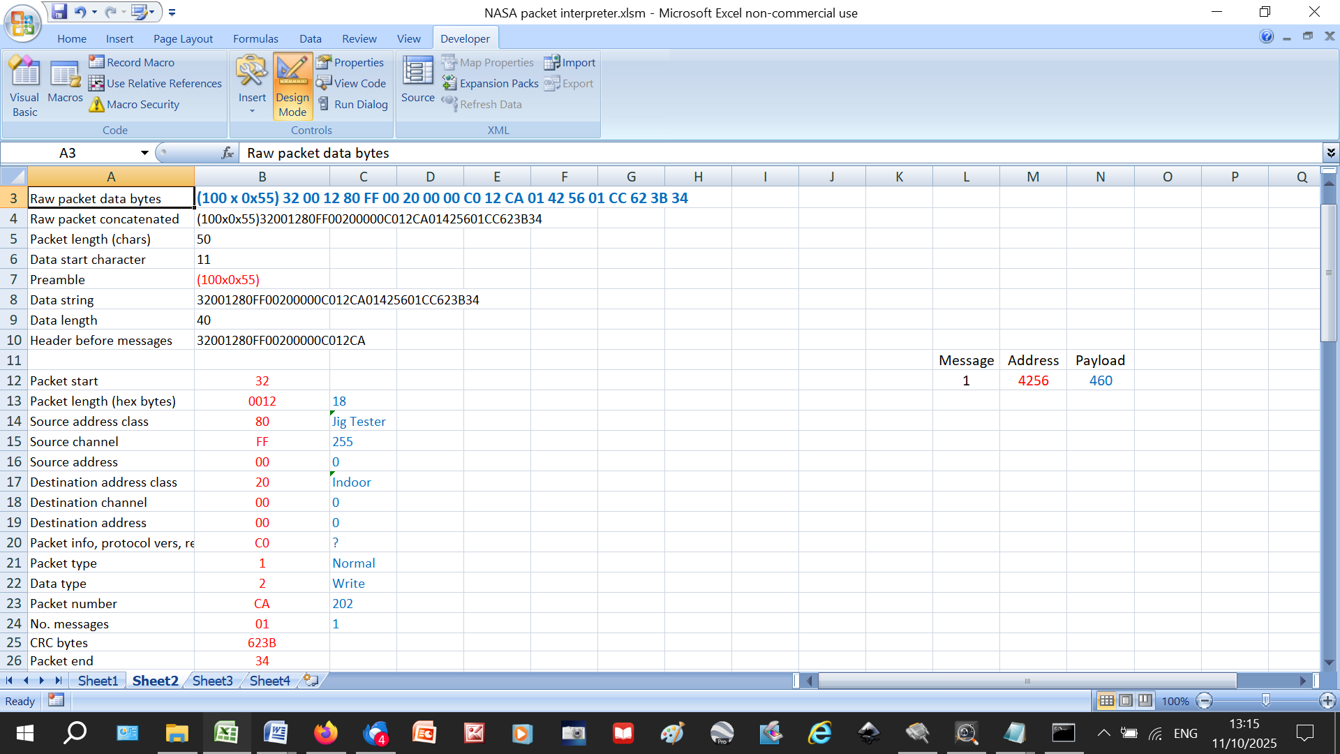
Out of interest, here is the traffic seen by my proxy when I change #2021 using SNET:

[2025-10-11 10:40:21.644] [OUTGOING] (120 bytes): (100 x 0x55) 32 00 12 80 FF 00 20 00 00 C0 12 CA 01 42 56 01 CC 62 3B 34

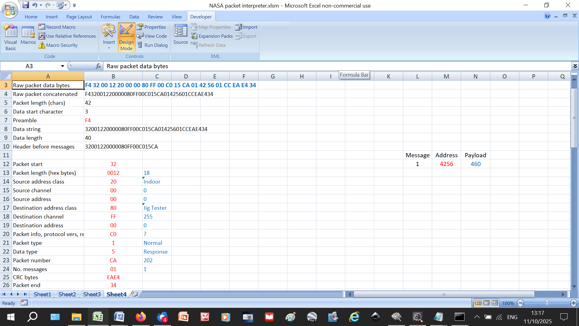
[2025-10-11 10:40:21.790] [INCOMING] (52 bytes): 7D FD 32 00 30 10 00 00 B0 00 FF C0 14 0A 09 82 33 00 44 82 98 00 00 82 A8 00 44 82 A9 00 44 82 AA 00 00 80 3F 00 82 43 00 00 82 35 00 00 80 BF 00 DE 60 34

[2025-10-11 10:40:21.811] [INCOMING] (4 bytes): F9 FD FD FB

[2025-10-11 10:40:21.842] [INCOMING] (21 bytes): F4 32 00 12 20 00 00 80 FF 00 C0 15 CA 01 42 56 01 CC EA E4 34

You can see the Response to the update request coming back a fraction of a second later:

Interesting stuff.

My choice of FD etc. was based on what I saw in the ‘scope traces coming from the Outdoor and Indoor Units. I can’t easily reproduce exactly what they were sending, as their characters were 4 bits long, but as far as the receiver is concerned it should look roughly the same at the RxD line of the UART. I could easily have reproduced the 100 x 0x55s instead, but I don’t think it is terribly important, or even needs to be there at all on a lightly loaded bus.

I just copied what I saw the Modbus interface was sending, with the source class changed to WiFi Kit so there wouldn’t be 2 Modbus interfaces on the same bus in case that upset things. I don’t really understand what the channel field does. The address is more straightforward. Looking at the data sheets for commercial devices that talk to the NASA bus, they mention that the addresses of the devices on the bus can be set manually or automatically. I guess in our systems it is done automatically at start up and the outdoor and indoor unit get address 0

The difference between Request and Write is interesting. The response to a Request is an ACK, whereas the response to a Write is a Response, so you can immediately tell that the write has succeeded.

For my reliability testing I started adding in decoding of more registers, so I thought monitoring the refrigeration circuit would be interesting. It turns out you can’t monitor the Evaporator Out temperature on a Gen 6. Reading Suction Temperature returns a value of 0xFFFF (which seems to be the value returned for unimplemented features, despite it also being a valid temperature). Looking at the P&ID for the Gen 6 confirms there is no such sensor, whereas on the Gen 7s there is.

Can you post the Gen 6 PFD here please Alun? (It doesn’t seem to be on the Midsummer website - normally my go-to for technical data.) The HTQ series is far better instrumented…

…even though some Samsung terminology is a bit confusing (like they call evaporator inlet “condenser outlet” - probably a relic from the days of air conditioners).

[I wonder how suction pressure is controlled if there’s no suction temperature sensor?]

BTW do you have SNET-Pro2? If so could you also post an example Excel log from it? Many thanks.

I found it here ……

pp. 202 has the standard Gen 6 diagram, pp. 201 has the HTQ (but not as detailed as yours).

Yep, although the Samsung naming is consistent with AC cooling terminology, some of the comments added in Samsung NASA Codes document are (helpfully?) wrt to AC heating. Confused me until I got graphs of the measurements and thought “that’s not right, and that’s physically impossible”

No, the only reason I would need SNET is to update firmware. I would imagine there won’t be any updates now since the Gen6s are getting a bit long in the tooth, but that was one of the reasons I bought one. From an (old) engineers’ perspective, you don’t buy something that’s hot out of the development labs (because it’s going to be full of bugs) you buy something that is just about to be superseded (because most of the bugs will have been kicked out of it).

That remains a mystery. I looked at the wiring diagram for the Gen 6s and it does have more sensors, both temperature and pressure, but they are marked as optional. Looking at responses from candidate registers they all return 0xFFFF, indicating not implemented/fitted.

I have a question that SNET might be able to answer. I am looking at what I think is EEV position, register 0x8229. It seems to return values between 2000–0, which I assume corresponds to 100–0%. When the heatpump is inactive it sits at 100%, and immediately goes to a few % on start up. It occasionally wanders about between 100 and a few % during operation. What does the EEV position value look like on your Gen 7?

For me, through F3/F4 as it’s not connected to F1/F2 bus but through the indoor controller, I don’t have any value, the controller must not be storing the value from the outdoor :-

Maybe Samsung just look up the saturation temperature at the known suction pressure (using the table at the bottom of NASA.ptc), perhaps adding a small margin to account for a bit of superheat at the evaporator exit. What I see on my HTQ is that suction pressure is maximised consistent with ensuring (just) a couple of degrees of superheat at the exit (and similarly, that discharge pressure is minimised consistent with ensuring that the R32 is just a couple of degrees subcooled at the condenser outlet). So, 2 variables (suction and discharge pressure), and two knobs to twiddle (main EEV and inverter frequency). There’s likely some complicated interaction in the algorithm, but I’m inclined to suspect that the EEV is the main actor in suction pressure control, and inverter frequency in discharge pressure control.

On the subject of EEVs, yes you are correct that 0x8229 is the main EEV, and that 0-2000 is the digital output to the EEV actuator. Whenever the compressor is stopped the controller opens the Main EEV fully to flatten the circuit pressure, thus minimising the risk of compressor damage from reverse flow. (On the HTQ, it also also opens the compressor recycle valve for the same reason, but it looks like there isn’t one on the Gen 6.)

As for Main EEV position, mine spends most of its time modulating in the range 200-400, but hits 2000 during defrosts.

Please do. I don’t seem to have the ability on here

Just catching up a bit on this thread. It sounds like the conclusion is that anything you can do through F3/F4 you can do through F1/F2 ? The difference is that F3/F4 can provide power but is otherwise part of the same BUS?

The only thing I wasn’t able yo do on f1/f2 is setting ambient temps to replace wired controller and use custom thermometer spread into my house. Other than this everything is doable on f1/f2.

F3/f4 doesn’t allow access to outdoor vamues such as suction /conditionner out sensors. or eev value and also currebt compressor frequency. So in the end I added a f1/f2 rs485 interface too. But I kept f3/f4 to ensure I can set the current ambient temps.

Cheers

You should be able to send a PM here. Click your icon top right in the light blue header, then there should be an envelope symbol. Click that, and again, and you should see a page with a blue box top right with the envelope again and “New Message”.
If not, post here again.

Super helpful thanks. Sounds like I may not need to go into f3/f4 but it’ll be foot to have your device if needed

Actually the first batch is sold out. Do I need to reissue one so that you could order one board?

Cheers

Hi @samskiter, AFAIAC the experts on Samsung comms are @Topaz and @toadhall. I merely use F1/F2 as a layman to monitor the Outdoor and Indoor Unit variables using SNET-Pro (which I think is really good even with its flaws). Never investigated F3/F4 so cannot comment, but if you want to try SNET have a look at Samsung ASHPs: Customising Your SNET-Pro2 Display .

Hi all,

Today I’ve started a new path. I’ll try to get some insight about DHW switch from within :stuck_out_tongue:

It won’t be soon, but the path is exciting!

Cheers

EDIT:

For anyone who might have asked himself if the hysterisis is configurable on E03(EC)N, the answer is no:

See that nice <= 10 check. The 10 is definitely not a variable here, and all value are *10 to avoid performing floating computation everywhere. Also it could therefore be changed to another value … with some efforts

Here EVV states on GEN7 R32 units. When pump is off it reads 2000. After start it’s around 600 and slowly decreasing. What is it good for and is this good or bad ? :slight_smile:

Stage 2 complete, Heatpump is now controlled over NASA instead of Modbus

  • I moved over to a straight USB<>RS485 converter since I no longer need the hardware debug capability of USB<>RS232<>RS485 setup.
  • I changed the NASA “Requests” to “Writes” as noted by @SarahH since the Request just responds with an ACK, whereas the Write responds with a Response containing the value written.
  • When I was testing the new RS485 interface I had the debug USB<>RS232<>RS485 connected as well. The Bus Quiet Timer was the same for both interfaces so there were many collisions. The Bus Quiet Timer Period now randomly dithers +/-200ms about a mean of 2 seconds, now no collisions.

For the record, these are the NASA registers I am writing to

  • 0x4000 - Indoor Unit On/Off
  • 0x4046 - Silent Mode On/Off
  • 0x4247 - Leaving Water Temperature Set Point

and the NASA registers I am monitoring

  • 0x4236 - Return Water Temperature
  • 0x4238 - Leaving Water Temperature
  • 0x42E9 - Water Flow Rate
  • 0x8204 - Outside Temperature
  • 0x8238 - Compressor Frequency
  • 0x82E7 - Evaporator Out Temperature - but no sensor physically fitted
  • 0x8218 - Evaporator In Temperature
  • 0x82DE - Condenser Out Temperature
  • 0x820A - Condenser In Temperature
  • 0x823D - Fan 1 Speed
  • 0x823E - Fan 2 Speed
  • 0x8229 - EEV position

My HEMS deals with Weather Compensation, Scheduling, etc. so I avoid most of the FSV hassle.

Sarah has pretty much answered this above ………