I think SNET-Pro2 has a lot going for it - it’s the only monitoring I have installed (no need for a Raspberry etc.), and cost me less than £25 to set up (a little dongle I bought off Amazon - see the Monitoring Your Samsung ASHP Controller thread for details).
It does have several shortcomings - the built-in graphical capabilities are rather clunky, it doesn’t report Outdoor Unit energy consumption (only compressor current, which you need to correlate to total energy if you want to calculate your CoP), and occasionally the screen locks up and you have to reload, but the spreadsheet it downloads is brilliant for studying what the controller has been doing after the event (e.g. see the Samsung ASHPs: Anatomy of a Defrost thread).
I should emphsise that you can’t change any of the Outdoor Unit variables with SNET (though you can change any FSV with it).
If you are interested in the workings of your controller, SNET + dongle is a lot cheaper than the SNET + MIM-C02N or Modbus + MIM-B19. Go for it!
I ended up with an Atom Lite using a branch of the code you quoted. The branch just adds custom
climate which allows writing to some other registers (water law offset).
It has given me what I needed to integrate my Samsung HTQ with Home Assistant.
Topaz’s code does look better but I needed something for ESP.
Actually, the ESP way is not impossible. My code can also run in a docker aside home assistant, and you could just have the ESP as a bridge to connect F3/F4 (or F1/F2) to the python.
Cheers
That could work, at least for reading values. There is a project called stream_server described in this discussion that will just forward the rs485 data, but I don’t think it is two way (not expert enough to read the code!)
The m5stack is nice bit of kit costing just over £20, relatively simple to set up and then provides a rs485 to wifi bridge. The ESPHome platform does require applications to be written in c++ though.
The Waveshare RS485 to Ethernet adapter achieves the same ends, and at around the same price, and with absolutely no coding required. I described the setup details in Monitoring Your Samsung ASHP Controller.
I wouldn’t imagine someone would dare try this piece of cranked code
I skimmed through the github bridge link you provided. It sounds like the esp is opening a tcp port and broadcast what was received on the rs485 to connected client on that tcp port.
1/ You have to deploy a MQTT server (or you already own one (I do not support login/password on MQTT because reasons))
If you do not already have one, I suggest this docker-compose conf:
Then you just docker compose up and the MQTT server instance should be ready.
prepre-2/ clone my github samsung mqtt bridge to retrieve all scripts and various files.
pre-2/ install dependencies for mqtt bridge to work:
pip install -e requirements.txt
2/ you run the Samsung NASA bridge to connect the ESP stream_server and the MQTT server. python samsung_mqtt_home_assistant.py --mqtt-host <mqtthostname> --mqtt-port <1883 in my example docker compose> --serial-host <ESP IP/hostname> --serial-port <ESP stream server port>
You can add the --dump-only parameter (I used it when I was sniffing the F1/F2 link using a MAX485+FTDI, it worked pretty nicely.
And it should be pretty much it.
If you do encounter any weirdness, feel free to DM.
Cheers
After an epic and hectic final debug session this morning, I finished the USB Adapter for F3/F4 communication with the Samsung EHS ASHP (mainly the controller board)
Here are the firmware and hardware design files for those interested: GitHub - 70p4z/samsung-f3-f4-usb-adapter: An open hardware + firmware USB to F3/F4 bus adapter. To be able to converse with the Control Layer of Samsung EHS systems
I’ll be selling assembled boards for those who don’t want to make them themselves. PM me if interested. It should be less than 10$.
It replaces the MIM B19N. It can connect with a wired controller still connected. It allows to set almost all FSV, and allows for bridging with home assistant. This is merely a USB to modulated RS485 adapter.
Cheers,
Good work @Topaz, I’m sure that your board will really help Samsung owners optimise their circuits without spending a fortune.
However, I think that I should manage Samsung owners’ expectations about learning much about their Outdoor Units (OU) and their controller algorithms, either using your USB adapter+F3/F4 terminals or an RS485 adapter+F1/F2 terminals.
I’ve recently spent some time trying to reverse engineer some of the algorithms based on measured controller I/O data, but with only limited success. The main problem seems to be the lubricating/seal oil, present especially in the compressor but to a lesser extent around the whole circuit (due to imperfect oil separation at the compressor discharge). Based on my calculations, the oil is about ~5wt% of the refrigerant flow in the compressor. This doesn’t sound much, but it has a dramatic effect on the fluid physical properties compared with pure refrigerant (being miscible with refrigerant, the oil changes the whole P-H saturation diagram).
So anyone trying to do a thermodynamic analysis of the Freon circuit is likely to be disappointed, because Samsung don’t supply us with a Heat & Material balance for the various operations. For example, based on the indicated compressor discharge temperature, its calculated polytropic efficiency is >100% based on pure refrigerant. (The latter is likely because the cold oil desuperheats the refrigerant within the compressor as well as lubricating/sealing it – and it’s cold because it contains dissolved refrigerant that flash cools on its return to the suction.)
In summary, I’d advise against trying to understand the OU, not least because there’s nothing we can do about its operation other than minimise the LWT…
@SarahH I understand your point. However, here, the goal is merely to get intel and be able to drive the heatpump more conveniently.
For example I read about hysterisis troubles in another post. The MQTT link allows for example (at least that’s wjat I implemented) to have a 0.2C hysterisis on my floor heating and a 0.5C hysterisis on my radiator zone. It sure makes it more confortable compared to the samsung’s default 1C hysterisis.
Cheers
I have not used any of your code because I wanted to apply a similar methodology as the rest of my automation hacks and use ESP Home. But you did inspire me to investigate the F1/F2 communications to replace my Modbus Home Assistant integration.
NASA seems to give a lot more information and at a better update frequency than is possible with Modbus.
I have also made the ESP interface standalone capable so if Home Assistant goes down it doesn’t affect the heating system.
I did try the using the PWM pump limit controls using F1/F2 but found on my system it still ran the pump at 100% for the first 9 minutes. In the end I have used the ESP as a “PWM Translator” which looks at the Samsung PWM output, applies rules (different flow rates for hot water and radiator circuits, soft start, valve changeover etc) and then provides the output to the PWM pump. This has proved very successful.
It does seem that the Samsung control logic is quite crude but as a system, can be improved with a few tweaks.
The biggest issue I have with my setup is the fact that the 8kW HTQ has a poor modulation range.
As an example of the weird output you can get if you do use SNET-Pro2 to interpret the controller output data, take a look at this screenshot of its output over a recent 1-minute time span:
In the space of 10 seconds (07:39:30 to 07:39:40), the compressor frequency reportedly fell from maximum (60Hz) to about half, the discharge and suction pressures both shot up, the main EEV closed quite dramatically, and even the ambient temperature suddenly increased by 0.5degC.
More significantly, the reported RWT and LWT both suddenly increased (by 10degC and 8degC respectively). As a result, my calculated heat output (last column, in italics) almost halved.
It appears that either the controller is fibbing with its F1/F2 output values, or else there is a bug in SNET where polled RS485 values get jammed at particular values for a while. Either way, it is making analysis of controller algorithms tricky to say the least.
It would be interesting to hear whether NASA/Modbus users are seeing similar “jammed” data at F3/F4.
My Gen 6 Samsung does exactly the same thing. However, since it generally runs OK for hours on end I am not too worried with the occasional 9 minutes at 100%
I would be the same but we have an 8kW HTQ that has very poor modulation range (minimum output 4kW ish) and every time it cycles, the pump
restarts at 100% for 9 minutes (even if you set the FSV to pump max 70%).
Also by controlling the pump speed better, the Samsung DT control seems to start working and works better than when it starts at 100%. If you select 70% inv pump max, when it actually starts at 100% and after 9 minutes suddenly drops to 70% it can cause the LWT to overshoot and stops the cycle. A very poor implementation of inverter pump control overall.
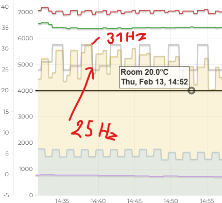
right now I control the heat pump over modbus and 0-10V
but I am little disappointed cause if I limit the frequency it still jump between 300-700W and its not efficient.
How you can change the hysteresis?