@Kocta Interesting!
Are you using frequency ratio control (DR) to limit the compressor speed?
Have you tried Modbus and the 0-10v (I believe they are the only methods listed in the manual)? If so which is working better for you?
Thanks,
Paul
@Kocta Interesting!
Are you using frequency ratio control (DR) to limit the compressor speed?
Have you tried Modbus and the 0-10v (I believe they are the only methods listed in the manual)? If so which is working better for you?
Thanks,
Paul
I tried both, you can write to a register but it’s only for about 1 hour then it goes back to normal, you need write again to the register.
If you use an analog signal, it has to be activated in FSV
0V = 50% 32Hz in my case
In mine opinion it is more convenient, but don’t expect to much from it.
Actually, I’m using HA to enable/disable zone depending on ambient temps.
I could also do it through water temps, but I think it would cycle more.
I didn’t realise the limits were so limited, it’s probably not going to help much as ours rarely runs more than 25hz other than initial startup. Thanks for the feedback though, saves me wasting time trying it out.
Hello, I’m interesting in this!
Dear all,
After more testing, it appears that without my reel of wire between the HP and my module, the communication doesn’t go through. So I’ll look into it more deeply before sending any board to anyone ![]() I don’t want any on-the-field failure!
I don’t want any on-the-field failure!
Cheers,
Guys, it is possible control field settings with this as well ? I have MIM-B19N in indoor unit but some of the NASA protocol messages simply are not working with this.
I’m especially interested in these values:
| 0x4254 | VAR_IN_FSV_2011 | Water Law Auto heating ambient temperature - Max. | ||
|---|---|---|---|---|
| 0x4255 | VAR_IN_FSV_2012 | |||
| 0x4256 | VAR_IN_FSV_2021 | Water Law (WL1-Floor) Temperature auto heating - Max. | ||
| 0x4257 | VAR_IN_FSV_2022 | |||
| 0x4258 | VAR_IN_FSV_2031 | Water Law (WL2-FCU) Temperature auto heating - Max. | ||
| 0x4259 | VAR_IN_FSV_2032 |
Modbus interface module is connected to outdoor unit. I’m using RS485 to USB adapter connected to rPI. I wonder where do you connect the USB reader to use with NASA link ? It’s connected into control kit (MIM-E03CN) or I also have wifi kit and I’ve seen some connectors there as well. Thx.
Hello, if I understand correctly you can’t access all the fsv you’d like.
I connect the USB<->F3/F4 directly on the E06cn indoor unit.
All the fsv you mentionned are fsv that I’ve already integrated and that I control through home assistant.
cheers
Hi, yes exactly. Not all are available via Modbus interface so your solution sounds better for me. What RS485 to USB adapter do you use ? I have this one so I guess it could work for this as well ?
Thanks.
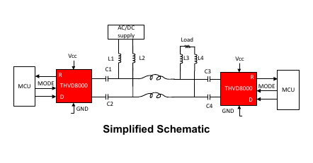
The F3/F4 RS485, is a modulated RS485, I use a THVD80x0 chip behind a RS232 USB converter. But the PCB I’m finalizing (sounds like it’s an analog filtering issue I’m running in) is implementing exactly that.
Ah, so theoretically my converter could work as well, right ? I just need to disconnect it from Modbus interface module and connect to F3/F4 on control unit ? Mine is using FT232RL chip.
Not exactly, you do use RS485 modbus, but it’s not a modulated modbus. The THVD80x0 chip from TI is doing a very particular job to carry RS485 over a DC line. You could damage your USB-RS485 device if you try to connect it.
Hi Topaz,
I’ve never heard Modbus described that way.
Could you elaborate a bit on what you mean by modulated?
Thanks!
Hello @Bill.Thomson,
I’m glad you asked. It bothered me at first too. I had some time to figure out what was the protocol in use on F3/F4 using the oscilloscope.
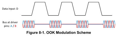
Here are snapshots of the THVD80x0 chip datasheet :
As you can see, the USART is D, bits are respecting the RS485 way of operation, but instead of simply applying a differential voltage between A and B, an OOK modulation is applied between the wires. allowing for transport of the data over a DC line (hence allowing data+power over 2 wires), it comes very handy to power remote controller as well as communicating with them.
In hope it made the thing clearer.
Cheers,
Amazing work @Topaz, I’m interested in buying the PCB.
Hey folks,
Ok, I took my sweet time but finally the PCB is working real nice.
I’m about to send the card to production, I can assemble 3 PCB without overhead (but the time to assemble them)
They have a USB micro B connector on one side and a 2 pin screw terminal block (A/B).
The PCB enumerates itself as a generic com port (ttyACMx on linux). And it only takes the python script to run on the host. A dump only mode exists to still rely on samsung wall remote controller.
For a long time I have been running the PCB in addition to the remote controller. The remote controller would update its display depending on configuration sent by the python script. It makes a nice house display.
Anyway, I’m about to launch a batch fabrication of these tiny things. I plan to sell them 15$ each. It only requires a USB cable (although upon special request I could provide with dupont wire connection to bypass the usb/serial converter and directly connect boards such as raspberry or ESP).
Please send me a PM if you’re still interested. I assume it could be ready to ship before end of june.
Cheers,
Super interested in your circuit! It sounds like everyone is pretty confident that F1F2 is a no-go for Reading/Writing FSV and full access to NASA?
I’d love to have the option of USB or dupont connections as unsure how I’d use it!
@samskiter, OK i’ll reserve one. They’ve been shipped today. shouldn’t be too long
The dupont option is a way to bypass the usb<->serial converter; hence allowing, for example, to plug an arduino or raspberry pi onboard uart (+tx_enable pin) directly to NASA, saving the USB port of the raspberry pi board for another use.
Anyway, I confirm F1/F2 does not accept changing the FSV. The samsung controller board does not accept the same instruction set on both link. The controller assumes the F1/F2 is only connected to the outdoor unit(s). But on that link, you can read the effective current sense and compressor frequency, I’ve already played with that monitoring. But previously I had no plan of modifying data exchanged on F1/F2.
However, for a CoP subject on DHW, I plan to perform a man-in-the-middle protocol hack between the outdoor unit and the samsung controller. I want to set a max water flow target. This would enable to avoid my tiny DHW coil to require higher temperatures, but instead, run longer with a better CoP. Hopefully, that hack does not require but two simple RS485 transceiver (and probably a board in between to allow for hard coding of the hack, hence avoiding potential heating problem when home assistant is down ![]()
Cheers,
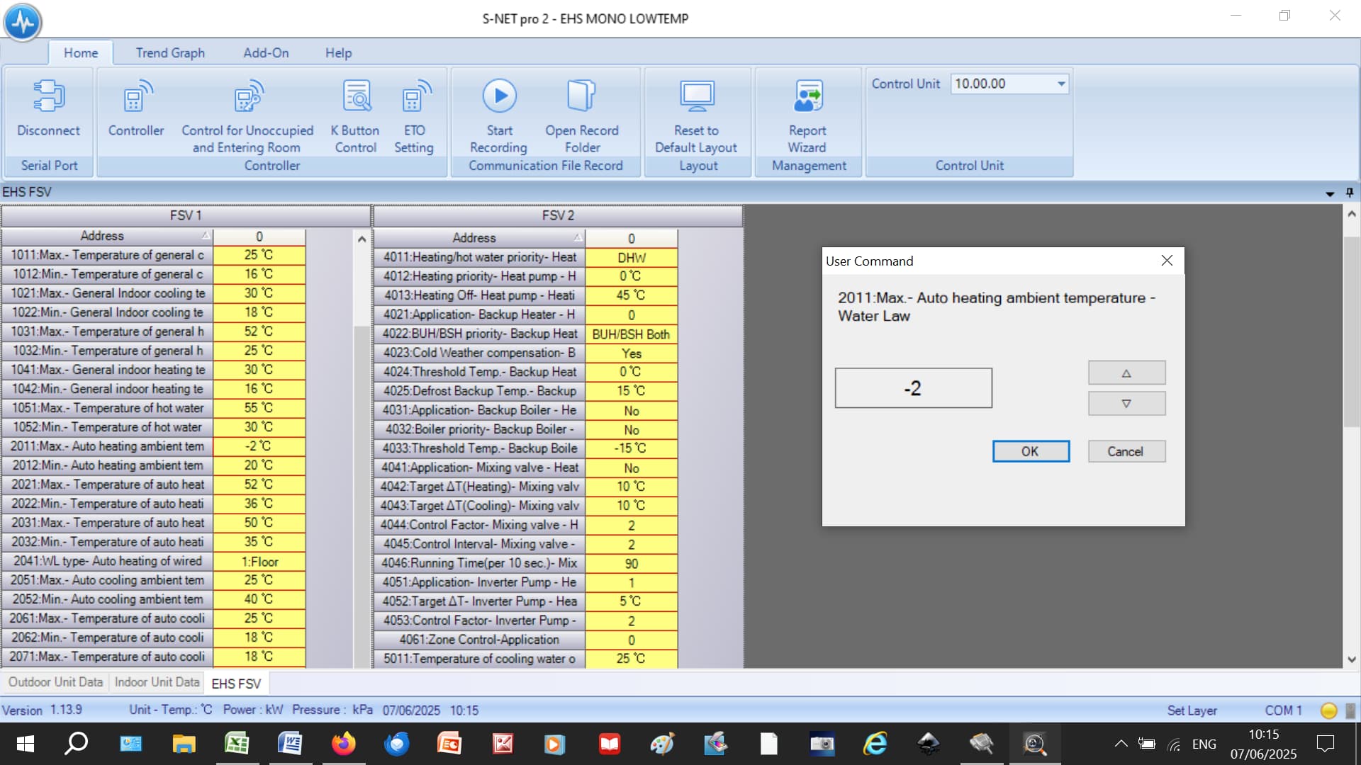
I hate to disagree with you @Topaz (your grasp of Samsung comms is way ahead of most folk), but the Samsung SNET-Pro2 software does just that - it allows me to manually update all my FSV values from my laptop via F1-F2. So if SNET can do it, I assume that anyone with sufficient knowledge of the Samsung NASA protocol could write a customised version that responds to some sort of optimisation routine.
Here’s a screenshot of my SNET:
You can see that, as well as an Outdoor Unit and Indoor Unit tab, there’s an “EHS FSV” tab. In the screenshot, I’ve elected to adjust #2011. (I just double-click on the FSV I want to change and get the sub-window you see on the right.)
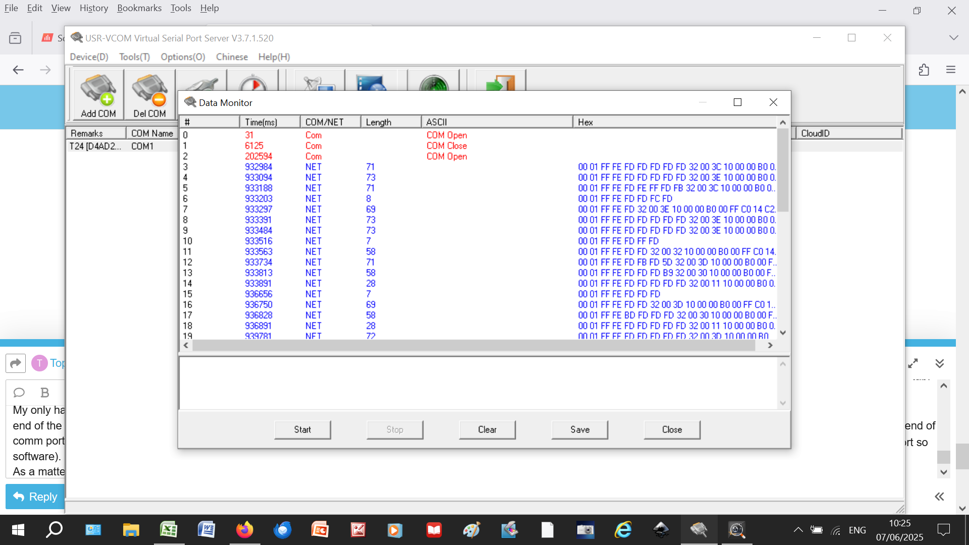
My only hardware is an RS485-to-ethernet adapter connected to F1-F2, with the other end of the ethernet cable connected to my broadband router. I had to install a virtual comm port so that SNET recognises the incoming signal (easy using free-to-download software).
As a matter of interest, you can see the NASA messages using the VCOM software in-built monitor:
Presumably, any home-built interpreter software would have to adopt the same protocol for any Write operations.
BTW, the Samsung EHS Wiki data table showing the controller register functions has been removed. Here’s an MS Word version to keep you going:
Samsung NASA Codes.docx (77.1 KB)
I totally agree with you, but I couldn’t found a way to sniff that on the link, I’ve tested connecting SNET using a usb com to rs485, and it clearly didn’t work the way you show us. So I dropped that part and went the modulated F3/F4 way.
Can you try to modify the ambient current temperature (not the target) through F1/F2, this is my main problem, as I have replaced (disconnected) the wired controller and replaced them with my own sensors to multiply the point of sensing.
I could make good use of the traces you provided to implement that transport and make the MQTT. I’ll have a look at that!
Cheers