I have just rejoined the forum after a break of a few years. ( House move, no PV at “new” house .)
At the “old” house I had successfully run Robin’s Mk2 PV Diverter for several years. I had modified the system to run multiple loads on a hierarchical structure.
Kettle
Immersion Heater
Mobile socket for any heating load:- sandwich toaster, slow cooker etc
Underfloor Heating In Bathroom
Heater in tumble drier
Oil filled radiator for space heating
After three years I am now about to have PV installed at the “new” house - 6kW PV system with battery storage.
I am about to dig out the diverter hardware from the garage & reinstall it.
Having looked at the website recently I realise the hardware has improved & moved on. I intend to fit my basic PV Diverter for now & “modernise” later.
I also have electric car charging to incorporate.
My query is, the battery system obviously measures any “spare” power available & charges itself, I don’t know how the system works yet.
Questions:-
How will the PV Diverter interact & work with this system.
Will each system interfere with the other?
Will battery system have priority over the available spare power?
Robin’s system and software is still available to constructors - all the (modern) details are on his website https://mk2pvrouter.co.uk/
There’s no reason why the two or more systems won’t work together - but each must not try to steal from the other. There’s a thread running at the moment about this, and I solved a similar problem with another user some while ago.
You’ll need to make sure that all systems can accept a control hierarchy. The system with highest priority needs to be seen by the one with the lower priority as part of it’s normal domestic load, and the higher priority system must not see the dump load(s) of the lower priority system(s).
The user whom I helped had just two systems - I think battery and water heating, and his problem was the two systems oscillated, stealing power from each other alternately. I suggested that he ran the wire feeding his immersion heater backwards through the grid c.t. of the other system, so its current in the main cable was cancelled out. So it knew nothing about the immersion heater, while the immersion PV system saw the battery charger as part of the normal house load, which automatically had priority. That solved the problem.
With the overall control strategy hopefully explained:
That depends entirely how the two systems want to interact, according to the type of installation the designer of the battery system envisaged or assumed.
Unless you do something like I’ve outlined, there’s every possibility of that.
If you decide that will be so, yes (given what I’ve written above).
[Edit]
Here’s the previous thread about a battery charger:
It occurred to me that if the tails are too large in diameter to share the same CT then maybe a second CT could be used which is connected in series with the first but in anti-phase on the other tail.
Don’t forget that a c.t. is a current source. Either a larger aperture c.t. or a second, connected in parallel, would suffice. But it’s early days yet to be specifying components.
We don’t know what the single-line diagram of the installation looks like. Very much depends on the physical layout of the wiring, and that’s never installed for the convenience of advanced control & monitoring.
Well, the PV system is now installed :- 6kW of panels & 4.5kWh storage battery. Just getting used to the system & working out how it all works together. Despite the cloudy day, the battery was fully charged by lunchtime & I was exporting all afternoon.
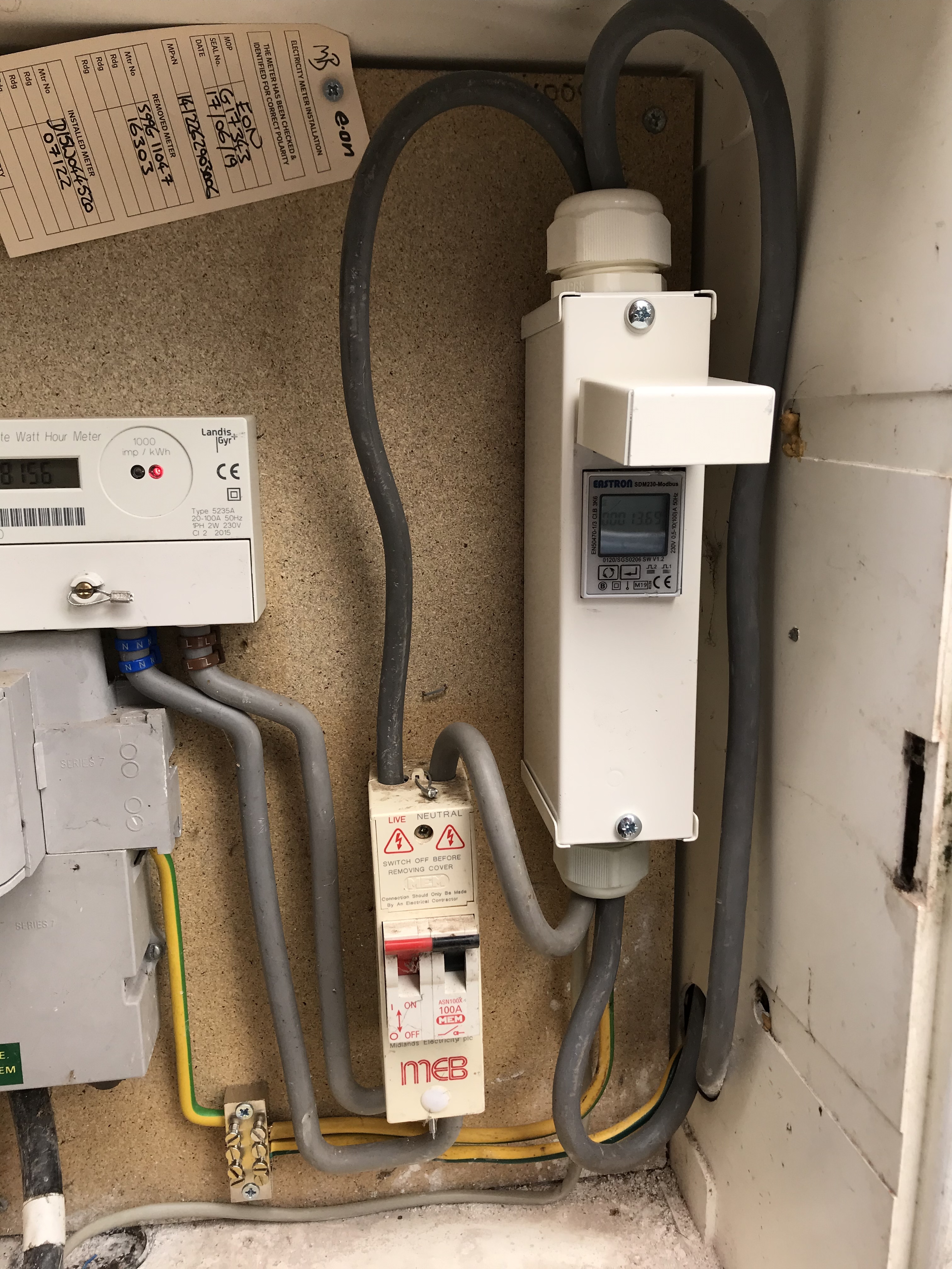
The first thing I noticed & probably a big problem with regard to reinstalling the PV diverter is the battery system does not rely on ct’s to measure the “spare” power. Instead, I have an Eastron SDM230 Modbus export meter fitted in the meter box. This seems to sense the spare power & feeds signal back via a data cable to the hybrid inverter. It is not possible to route the diverted power cable thru this unit as suggested.
How should I proceed reinstalling the PV diverter.
In the short term I’m switching to Octopus Energy so that I can at least get paid for my export.
The only way I can see to do that would be to add a Henley Block and a new consumer unit, feeding only the diverted load, between the main isolator switch and the supplementary Eastron Modbus meter, which presumably isn’t just metering export, but is differentiating between import and export and it’s the battery system picking out the data it needs. The diverter c.t. must be upstream of the Henley block.
“You might well find that the “energy bucket” the L&G meter uses is quite small, and the diverter may need tweaking to avoid overflowing the meter’s energy bucket”
Have now successfully run my old system on a test rig - worked as before, however when hooked up to my domestic system (with Landis & Gryr Meter) I seem to be importing power (red Light flashing every few seconds).
From what has been said previously the L&G meter has smaller energy bucket.
How do I “tweak” the PV diverter? Is it just a software change, if so what & where?
I am using a modified version of Robins REV5C Multiple Load code.
In the define statements are the lines:- #define CYCLES_PER_SECOND 50 #define JOULES_PER_WATT_HOUR 3600 // 0.001 kWh = 3600 Joules
#define SWEETZONE_IN_JOULES 3600 #define REFRESH_PERIOD 1000 // max period (ms) between RF messages
Is it just a mater of adjusting the “SWEETZONE” statement to 1250 to suit the L&G meter?
Yes, that’s it. I wouldn’t bet that 1250 is the correct value - you’ll need to adjust it in the light of experience and in any case, yours must be smaller than the meter’s.
But you might like to consider moving to the successor “Mk2_multiLoad_wired_7” version. I’m not fully conversant with the details of the changes, but in any case your own changes would need to be carried across into the V7, so I can completely understand if you don’t want to go that route.
I’m unable to use the Mk2 multi load wired version as all my remote loads are wirelessly connected using rfm12B units.
I presume I would have to change the “3600” that occurs later in the code as well.
logicalLoadState[i] = LOAD_ON;
cycleCountAtLastTransition = cycleCount;
energyAtLastOnTransition_long = energyInBucket_long;
energyAtLastOffTransition_long = 3600 // reset the ‘opposite’ mechanism.
activeLoadID = i;
changed = true;
If I set the sweetzone much smaller than is necessary I presume I will force a net export. This might be useful to create a export buffer if needed. - I have yet to see how the old PV diverter system interacts with the new battery system yet.
Ah, as you were using the “wired” version, it was reasonable for me to think that you still wanted to use the “wired” version. There is of course the “Mk2_withRemoteLoad_5” sketch (and its associated receiver sketch). I suggest you look at Robin’s “Downloads” page at https://mk2pvrouter.co.uk/
Looking at that sketch, I think the things you need to change are WORKING_RANGE_IN_JOULES and possibly REQUIRED_EXPORT_IN_WATTS.
I don’t think that is correct - what will happen is the load will be switched more rapidly, hence the rate of any flicker will increase.
As I explained earlier, there is the potential for a feedback loop to be set up between the two systems, resulting in instability. The solution is to ensure the battery system does not see the dump load as part of the load it needs to supply, and the Mk2PVRouter sees the whole battery system as part of the normal house load - assuming the battery should have priority for the PV-generated energy. From your photo, it looks as if your dump load(s) will need to supplied upstream of that pesky Modbus meter - see post no.6.
When the Mk2 PV Router is used in its “Normal” mode rather than “Anti-Flicker”, there will only be one energy threshold. Its load(s) will be turned on/off as fast as is necessary to maintain the energy state at a near constant level. This will happen regardless of calibration and the values of various changeable parameters in the software. The switching rate is only dependent on those parameters when the Mk2 diverter is operated in its AF mode. If there is any doubt about a meter’s tolerance to a reciprocating flow of energy, “Normal” mode is always the safest setting.
Between the meter and your Modbus unit, there appears to be a DPST switch. This would allow the downstream wiring to be isolated from the incoming feed while a suitable connection for your dumploads is added.
A similar isolation switch allowed me to temporarily connect an analogue meter in series with our incoming feed for demo purposes. That disc-meter, since removed, has appeared in a handful of videos on the subject of surplus power diversion. This footage shows the original prototype hardware but the underlying principles have never changed. https://www.youtube.com/watch?v=WVqL30uOluQ