AC to DC Power Supply Design for PI/Arduino/ESP32 Electronics

Hoping to get advice on design input power to Electronics.

I have an Pi 4 running EMONCMS Version low-write 10.3.

An Arduino Atmega328 custom board is used to count water and gas pulses.

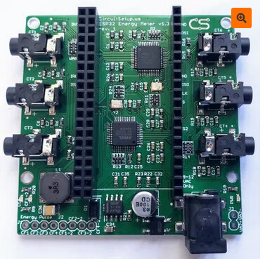
An ESP32 inserted on top of the 6 Channel ESP32 Energy Board sold by CircuitSetup.

Both Arduino, and ESP32 Energy Board programs have been modified, and wired serially to the Emoncms Pi for communications.

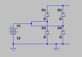
Currently, I am powering all three devices using the method in the drawing, which one 120/9 VAC transformer. I use the 9 VAC for the 6 Channel ESP32 Energy Board, then rectify, and use a 5 Volt DC to DC Converter to power the EmonPI and Arduino. I live in the States, and the power is clean and not many dips or spikes.

Attached is a drawing of the Power connection to all three connections. The drawing just represents the power section, much of the other electronics has been omitted, such as Input Pulse circuitry, digital inputs, relay outputs, i2c sensors.

I am building another one for our retirement home in the Philippines coming up in 2 years. Installing an EmonCMS metering will be a precursor to installing solar panels. The power in the Philippines is 220V with frequency of 60Hz. In the Philippines, there are frequent brown-outs, and I can assume the power is not as clean as the States. Probably many spikes and dips. So, I am worried that the Electronics will not last long using the present input power method.

I am considering an isolated DC to DC Converter to prevent spikes to the PI and Ardiuno? But, it appears the isolation would be defeated because the ESP Energy Board non-isolated ground is common with Arduino, and Emoncms PI. I believe, I needed to connected commons to get wired serial communications to work.

Another option I was thinking of is adding another ESP32. Isolate that ESP32 with the Arduino, and Emoncms PI, then radio the non-isolated ESP32 Energy Board data to the isolated ESP32.

Also, referring to the attached drawing is there potential for Ground Loops?

I am hoping to get Robert Wall’s opinion, since he usually replies to power questions in the community posts.

Thanks in Advance.MeteringPowerDrawingRev1.pdf (859.8 KB)

It seems that your main worry is the power supply quality.

How you are actually measuring the energy has quire a bearing on this - and you’ve left that off. If you’re using voltage and current transformers, then those aren’t a direct cause for concern.

Regarding the d.c. - d.c. converter on your diagram, it’s probable that input and output are isolated, because otherwise I think you’d have three terminals rather than 4, but confirmation by means of a statement in the documentation or a circuit diagram would be reassuring.

If your main concern is the power supply quality, then I’d suggest using a battery to provide the power to everything, using d.c. - d.c. converters where necessary, and simply charge the battery from the supply.

At a first look, it would appear that a 12 V battery would do everything you need - you could use the existing step-down convert for the RPi and the Arduino, and if you choose the correct input and GND, the ESP32 energy meter too. Bear in mind the circuit diagram for that is wrong, you use the GND as the -12 V supply and putting +12 V into a bridge rectifier just means 11.3 V makes it into the regulator. Silly as it might sound, you can use either or both VA+ & VA- like this:

Screenshot 2021-03-08 15:49:48

I’d suggest getting a proper regulated battery charger for the 12 V battery - your 120 V transformer will be redundant anyway.

Thank Robert,

I am Measuring Current via CT’s, and measuring voltage using 9 VAC, which is why I want to include the transformer in the same control box, and use it for both 5 VDC power, and 9 VAC to measure voltage. Otherwise, I would need separate AC supply to plug into the 2.5mm male connector of the Energy Board. Reference link and picture.

Concerning the d.c. - d.c. converter in the drawing, the negative (–) terminals are common, verified with ohm meter. But, I am considering an isolated DC to DC Converter to prevent spikes to the PI and Ardiuno? But, it appears the isolation may be defeated because the ESP Energy Board non-isolated ground. I am a beginner in electronics design, so I am not sure how well protected the Energy Board input power is. Maybe an isolated DC – DC converter would be good enough, assuming the ESP Energy Board is isolated or protected enough not to allow voltage spikes through to the Arduino, PI, and ESP32.

Thanks for letting me know about the incorrect bridge rectifier drawing.

The ESP32 in mounted into the Headers.
image

Is that the same 9 V a.c. as powers the d.c. - d.c. converter? If it is, all bets are off regarding the accuracy etc of your measurements, because there’s every reason to believe the waveform won’t be faithful replica of the mains voltage. It’s because the bridge rectifier connects each of the ends of the transformer windings to the positive and negative supply rails on alternate half-cycles.
You need a separate transformer, or a transformer with a separate secondary winding, to supply the voltage sample for power measurement. I can’t see a link to a circuit diagram of the ESP Energy Meter, so I can’t be absolutely certain that this will be the case. But I would be very surprised if it is not.

If you search the old forum, there’s a thread where a certain individual “invented” a single supply for his emonTx using non-polarised electrolytic capacitors “because it was a.c.”, oblivious of how a bridge rectifier circuit actually worked. Then he insisted our calibration maths was wrong because he needed a tweak pot to get the correct answer - not realising that the wave he was measuring was nothing like the true mains waveform. He departed in a huff, never to be seen again.

The emonTx V3.4 gets around the problem by having only a half-wave rectifier – and then you can use a single transformer winding for both power and measurement, provided you can accept the distortion that the current pulse at the peak of the wave inflicts.

I rather doubt that would totally prevent spikes, and it almost certainly won’t protect your Pi’s SD card from a sudden loss of supply. I would have much more confidence in a battery power supply supported by a charger – and that’s distinctly different from a mains supply with battery backup.

Thanks Robert,

I do appreciate your time and honesty.

Yes, the same 9 VAC does power the the d.c. - d.c. converter.
I am using that method right now, and didn’t notice a problem.
But then again, I didn’t scope the waveform. I just calibrated against a Fluke multi-meter.
I will scope my existing metering system, and share the results.

I do like the battery & charger combo for the Pi, and Arduino.

If I do use the battery method, and a separate 9 VAC supply for the ESP32 CircuitSetup Energy Board, then if I recall correctly. I still needed to connect the PI Ground to the ESP32 Ground to get the wired serial connection to communicate. Do you think sharing grounds will cause a problem?

Here is the Git Hub link to the ESP32 Energy Board:

‘’‘GitHub - CircuitSetup/Expandable-6-Channel-ESP32-Energy-Meter: Hardware & Software documentation for the CircuitSetup Expandable 6 Channel ESP32 Energy Meter’’’

It won’t be supplying the operating power for that, only providing the sample voltage for it to measure. The power will come from the battery 12 V d.c.

The whole idea behind using a 12 V supply (or part of the idea) is everything is using the negative side of the battery as a common ground, so all the GND points will be connected, and everything is using the same reference. Normally, you get all the problems when various sections don’t share a common ground, and then you also need to isolate the signals that are passing between them. It gets very messy.

The only things that won’t necessarily be connected to it will be the voltage and current sampling transformers.

For more about the separation of the voltage sample from the power supply, read this: Learn→Electricity Monitoring→Voltage Sensing→Why Can’t I Use a Single Transformer?→Why Can’t I Use a Single Transformer?

Thanks for the Learn link about using a single Transformer. I shall read that tonight.

About the ESP32 power, I would have to re-design John deGlavina’s CircuitSetup Energy Board, because he is powering the ESP32 from the 9 VAC input. On the drawing it is VDD, and I measured it at 2.7 VDC.

URL: Expandable-6-Channel-ESP32-Energy-Meter/6_channel_esp32_energy_meter_1.3_rev1.pdf at master · CircuitSetup/Expandable-6-Channel-ESP32-Energy-Meter · GitHub

image

No you won’t.

His diagram is wrong - as the note says (and you’ve only got to look at it for a moment to see it’s wrong). It should be like this:

The diodes should ‘point’ upwards and the output is top (+ve) and bottom (-ve) and the a.c. feed is to the middle.
Now, you can connect the 12 V d.c. to GND (-ve) and +ve to the barrel socket, either centre pin or the sleeve or both in parallel. The LMR can accept up to 40 V input, there’s not much difference between feeding it 12 V d.c. and rectified and smoothed 9 V a.c., and it will be dissipating even less power than if you feed it 12 V a.c. - the voltage in that case on Vin is likely to be higher at around 16 V. And you don’t get a diode voltage drop between the two GNDs.

Obviously, I need to do some studying/refreshing to get a better understanding of circuit design. I thought the CircuitSetup Energy board required 9 VAC as a reference point for the 120 VAC measurement.

Appreciate all your feedback!

It may be a while, but will post my findings to this post.

Thanks again Robert.

Not according to that diagram anyway. I haven’t downloaded the full Eagle drawing - it’s too large.

I recall there was discussions at the time in this thread about the distortion the power supply caused on the AC signal.

A later version used a full-wave rectifier but I suspect that subjects the IC to unacceptable common mode voltages (although the limits on that aren’t specified by Atmel). That was further discussed in this thread.

I hadn’t remembered that - it was nearly 2 years ago. According to the stats, I’ve read 13,561 posts in the last 12 months alone, so I’m not very likely to remember one thread with something like 25,000 posts read in between.

You didn’t make it easy. I couldn’t read the PDF, now that I’ve managed to download the Eagle file, it appears that the power supply transformer is indeed used for the voltage sensing, which isn’t exactly compatible with the best accuracy. So I’ve been largely wasting my time because that isn’t shown on the drawing you provided.

You can still power the Arduino and the Pi and the ESP from a 12 V battery as I suggested, if you can work out a way to separate the voltage measurement from the power supply. The easiest way to do that is probably to remove the bridge rectifier and feed the 12 V d.c. at the + & - pads that it occupied, then the 9 V a.c. connector becomes just the voltage sample input.