ZMPT101B, powerfactor and current shown

I could see that Robert.Wall was able to show a 24 degree phase shift using a simulation. When you measured a phase shift of 35 degree how did you do that? is that something an oscilloscope can help with?

My oscilloscope is a very cheap DSO150. I have never owned an oscilloscope before, I just bought this oscilloscope to adjust the trim pot on the ZMPT101B so that I get a clean sine wave without any flattening.

edit:
(I just googled this, seems you need an oscilloscope with more than 1 channel, so i guess im out of luck, I could just plug in a phase shift amount, but it would be nice to verify it with a physical test, I may have to see if I can find an older oscilloscope with 2 channels someplace for cheap)

I also wonder if I could verify the phase shift in software with an arduino sketch. I assume to do this I would need to compare the output from the ZMPT101B to the output of my mains AC, but obviously I cant do this directly because the Arduino due cannot take more than 3.3v to any of its inputs.

I am assuming I could hookup my AC-AC adapter with approrpiate circuitry to one input and the ZMPT101B to another input and compare the phase shift that way.

I am thinking if the only big problem with the ZMPT101B module is the phase shift, if I can verify the amount of phase shift and set it properly as done in the 3 phase sketch then I can just use the ZMPT101B as is and adjust the sketch.
My thought was, whoever “designed” that didn’t know what they were doing. As it stands, for 50 Hz mains, the amplitude will vary due to frequency changes, and at 60 Hz, it’s further down the slope and it will change even more.

Note, I typed “voltage” when I meant current above - the module delays the voltage sample by 24°, so you must either delay the voltage itself by 336°, or delay the current by 24°.

That should be easy enough. Note there’s a resistor missing from the published circuit diagram - as it is the c.t. input is held down at the negative rail, so it won’t work.
If the 100 Ω (R11) gives you adequate voltage into your ADC, then just lift off either C1 or R2, leaving R3, R8 and the one that’s missing to bias it to 1.65 V (or 2.5 V as appropriate). You’re actually back to our standard c.t. input circuit when you do that. All you’re really interested in is R12, the multiplier resistor which converts the mains voltage to a current, and R11, the burden resistor which converts the output current back into a voltage. The data sheet for the ZMPT101B gives all the information you need.

I don’t think that would be the fault of the a.c. adapter, was it the sketch out of the ‘Learn’ section that you were using?

I never watch videos, so I’ve no idea what it said, nor whether it was correct. The two op.amps work in roughly the same way. They are “inverting”, so the output goes down when the input goes up, and vice versa. The combination of C1 & R2 forms a high pass filter (removing low frequency components), likewise C4 & R6. These are responsible for the output rising from 0 mV on the left of the graph towards a maximum on the right.
C1 & R1, also C3 & R9, also pass the high frequencies, but as these are feeding the output back to the input and tending to cancel out the input, the effect is to reduce the high frequencies in the output. These are responsible for the output falling from the peak at about 30 Hz.

If I had designed that circuit, I would have made C2 & C4 a lot larger, and C1 & C3 a lot smaller, and I would have left the adjustment out and designed for a lower gain. That way, you would not get a peak like that.

1 Like

Using a slightly more accurate op-amp model, my LTSpice shows about 20° phase shift at 50 Hz, and about 15° at 60 Hz. Just increasing C2 & C4 to 10 µF and reducing C1 & C3 to 470 pF reduces that to about 0.6° lead at 50 Hz and 0.1° lag at 60 Hz. Amplitude variation is small up to the 3rd harmonic - maybe 0.2% down.

This is only a Spice model - it might not be quite like that in practice.

Not necessarily. If your DSO has an external “sync” input, or even better, if it can sync to “line”, then can you lock the trace to the mains voltage, note where the trace is on the screen, then transfer the probe to the module’s output and measure the time shift (and equate that to degrees)?

I don’t actually use a 'scope to measure phase shift - it’s very, very, hard to get an accurate value. I use a sound card and do a discrete Fourier on the values in a spreadsheet, and even then, I have to be meticulous in getting the two inputs exactly balanced before I try to take any measurements.

Do be careful measuring mains voltage. If you make a mistake, at best you’ll blow up your DSO. At worst, you’ll blow yourself up as well.

1 Like

@xekon I measured the phase angle between mains (250vac at the lab) and the output of the module powered by a cleanish 5V.
Yes, I used a 2ch scope. The 1000V rated high impedance inputs don’t cause too much added phase shift. If your scope can’t take the voltage, a resistor divider is fine enough to bring it down, just gotta be careful with that there live wire.
It’s an Okay scope I had access to, it automatically found the phase shift and gave me a value in microseconds of the shift, which I converted into radians (and then degrees) according to the frequency, which was 49.8Hz, or something thereabouts. phase angle in degrees is… (time delay/period)*360 … might need correcting there.
Interested to know if you get similar results or manage to get a clean signal from the voltage transformer without the smoothing (so the flat tops are visible), without the opamp! But it does sound like you need a better scope with more resolution.

At the moment my conclusion, similar to Robert’s but for different reasons it seems, is that the modules are useful as amplitude and frequency measurement devices, but not for super-accurate monitoring.

This discussion has got me thinking about another test to make on the transformer component, sans module, might have another go at it.

Well, my take on mains voltage… mains voltage is nasty, but not too nasty. If it were, it wouldn’t be in the walls of our houses. I’ve had a few shocks, not that bad. An experienced sparky said to me he used to test wires with his thumb nail. Could’ve been taking me for a ride. But I duly took it on board regardless, and after flipping a breaker for electrical work, I test wires (including neutral and earth) with my thumb nail before handling it properly, after all, better safe than sorry.
I jest, a little.
But get this. You might know, in the EU, the standard socket outlet is 230Vac and there is NOTHING stopping a child from sticking a metal skewer into that live connection. THAT is dangerous. At least in the UK we have the plastic gate-things which require an earth pin to be inserted for the live to be revealed and accessible.

Interestingly perhaps, I was going to say that since you’ve done your own wiring (first time?) you might want to get a professional to take a look. I wasn’t going to say this at first, didn’t want to patronise you. I’ve had the fortune of being shown how to do house wiring and take it for granted now, despite it not being my profession per se, really glad someone showed me.
And I read now… electrical fires cause many more deaths than electrical shocks. I don’t mean to minimise the deaths that do occur because of shock either.

If we’re going to talk safety, we might as well get our priorities straight innit.

For @xekon’s benefit, the standard UK plug looks like this.

Just to pick up on that point, that’s one way it’s done. The other way is a rotating shutter that needs both line and neutral pins to be inserted together to unlock and rotate it to allow the pins to enter and make contact.

And when @TrystanLea reads this: The plastic “socket protector” that looks like a very flat BS1363 plug, that’s sold to put in sockets to prevent children poking things in actually make the socket MORE dangerous than without it, because children have been known to pull it out, rotate through 180° and use it to open the shutter. :exploding_head:   :roll_eyes:

But we’re OT here.

We are. But I have to say, David Peacock was a bit of a dude. Good on him.
And that child in the video is remarkably adept at pulling those covers off, and that parent is rather relaxed about it. If I was looking after a kid I’d scare the shit out of them with a loud noise any time they put their hand on a socket. Pavlovian style.

I would be inclined to use covers anywhere else apart from the UK though. The saving grace of the EU socket be a very snug fit for a cover.

@xekon Op.Amps are very interesting right?
Continually hunting to balance the + and -.
The video’s okay but could be clearer at the outset about the IDEAL op amp. I read there were 6 characteristics of the ideal op.amp. That’s worth a look.

This is the sketch:

// EmonLibrary examples openenergymonitor.org, Licence GNU GPL V3
#include "EmonLib.h"             // Include Emon Library
EnergyMonitor emon1;             // Create an instance
String mystring = "";

void setup()
{  
  Serial.begin(9600);
  analogReadResolution(ADC_BITS);
  
  //emon1.voltage(0, 330.1, 1.7);  // Calibration for ZMPT101B Voltage: input pin, calibration, phase_shift
  emon1.voltage(0, 19800, 1.7);  // Calibration for AC-AC Adapter Voltage: input pin, calibration, phase_shift
  emon1.current(1, 103.1);       // Current: input pin, calibration.
}

void loop()
{
  emon1.calcVI(20,2000);         // Calculate all. No.of half wavelengths (crossings), time-out
  //emon1.serialprint();           // Print out all variables (realpower, apparent power, Vrms, Irms, power factor)
  
  float realPower       = emon1.realPower;        //extract Real Power into variable
  float apparentPower   = emon1.apparentPower;    //extract Apparent Power into variable
  float powerFActor     = emon1.powerFactor;      //extract Power Factor into Variable
  float supplyVoltage   = emon1.Vrms;             //extract Vrms into Variable
  float Irms            = emon1.Irms;             //extract Irms into Variable (currentDraw)

  //mystring = "V:" + String(supplyVoltage) + " PF:" + String(powerFActor);
  mystring = String(supplyVoltage);
  Serial.println(mystring);
  delay(300);
}

I think I figured it out. The AC-AC adapter I was using was not giving a proper sine wave or voltage when checked with the DSO150. I previously spliced a 3.5mm stereo connector as the end of the plug for the AC-AC adapter, because I had plenty of stereo jacks for the shield I made. however the size of the wire on the 3.5mm stereo connector that I spliced on is so small that it was messing up the signal from the AC-AC adapter. removing the stereo connector from the plug and checking the wires directly provided a nice clean sine wave. I am about to hook this power adapter up to the arduino shield without the stereo jack and see how it goes.

it is working now with my AC-AC adapter :slight_smile: YAY! The voltage is more accurate with this AC-AC adapter than it was with the ZMPT101B, with the ZMPT101B I was seeing +/- 1 volt. With the AC-AC adapter I am seeing +/- 0.1 volt.

I still plan to modify the ZMPT101B removing the op.amps to see what it does for it, however I now have a working system, about to do the rest of the calibration and make sure current and powerfactor all look right.

Yes, I found it very interesting indeed!

Now that I am working with the AC-AC adapter and trying to dial in the calibration with it, I have made a new thread (Arduino Due Calibrating Voltage sense +/- 0.1 at first, now +/- 0.3 what does it mean?) instead of continuing to post to this one.

I will come back here later when I play with the ZMPT101B some more.

1 Like

I am currently researching how this is done. I have like 10 spare sound cards sitting in a box.

Edit: I was reading earlier about sound card oscilloscopes and plan to give that a try. I know your not supposed to use a voltage divider for AC Mains directly with emon/arduino because it can be dangerous, but if your careful maybe its less dangerous for a temporary test with the sound card. What type of circuit did you use to interface your AC Mains with your sound card? (most of the circuits i see online are voltage dividers with diodes.)

edit2: I figured I would start off using the older/cheaper sound cards just incase i do happen to make a mistake and fry the card.

I am assuming your talking about adjusting your voltage divider so that the two voltages are equal.

Very carefully, bearing in mind sound cards only expect around 1V maximum input.

I use Soundcard Oscilloscope from Soundcard Scope

The spreadsheet is not that difficult, it’s mainly the same formula then copied 881 more times.
So rather than attaching the spreadsheet, here it is as instructions to type up (44.1 kHz sampling over 20 ms assumed - you need to change that to 16.666 ms):

(‘R’ = row)

Col A:
R2: “Time [sec]”
R3 - R884: the recorded time values.

Col B:
R2: “Amplitude”
R3 - R884: the recorded sample values for channel A.

Col C:
R2: “Amplitude”
R3 - R884: the recorded sample values for channel B.

Col E:
R2: “Sample”
R3 - R884: sample number starting at zero

Col F:
R1:“Output”
R2: “sin”
R3 - R884: Formula “=$C3SIN($N$3$E3)”

Col G:
R2: “cos”
R3 - R884: Formula “=$C3COS($N$3$E3)”

Col I:
R1:“Input”
R2: “sin”
R3 - R884: Formula “=$B3SIN($N$3$E3)”

Col J:
R2: “cos”
R3 - R884: Formula “=$B3COS($N$3$E3)”

Col L:
R2: “Harmonic”
R3: “step”
R5: “Output”
R6: “sum sin”
R7: “sum cos”
R8: “angle”
R9: “phase”
R10: “amplitude”

R13: “Input”
R14: “sum sin”
R15: “sum cos”
R16: “angle”
R17: “phase”
R18: “amplitude”

R21: “Result”

Col N:
R2: the harmonic number you’re analysing (usually 1)
R3: formula “=-$N$22PI()/882”
R6: formula “=SUM(F3:F884)”
R7: formula “=SUM(G3:G884)”
R8: formula “=ATAN2($N$6,$N$7)”
R9: formula “=DEGREES($N$8)”
R10: formula “=SQRT(N6N6+N7N7)/441”
R14: formula “=SUM(I3:I884)”
R15: formula "=SUM(J3:J884)!
R16: formula “=ATAN2($N$14,$N$15)”
R17: formula “=DEGREES($N$16)”
R18: formula “=SQRT(N14N14+N15N15)/441”
R21: formula “=MOD(($N17-$N9+180),360)-180”

Col O:
R9, 17 & 21 “degrees”

1 Like

Either way, the dangers are the same. If the neutral wire becomes disconnected outside or inside your home, or a neighbour on the same transformer does something silly, everything could become live to line. Everything, that includes the computer and anything that has a wired connection to it. So you are best using a laptop running on batteries with nothing else connected. If you have access to an isolating transformer that you can run your computer plus the a.c. adapter under test from, then do that, as it will isolate you from the supply. But you are still potentially handling live mains. You must still be extremely careful, and work out exactly what could become live in the event of a fault before you start.

I happen to have a transformer “ex equipment” that I found out was originally designed as a phase reference, so it has an extremely low phase error, so I use that. If you’re using resistors, use several lower value ones in series for the “top” part of the voltage divider - if one fails to a short, it won’t be a complete disaster.

Not only voltages, stray and cable capacitances as well as they will affect the phase measurement.

1 Like

I have a badly damaged UPS that I can salvage for parts, with two fairly large transformers in it, however I do not know if they are considered isolating transformers, I will need to research how to identify what type they are.

Without knowing the details of your UPS, it’s impossible to say whether it would be useful. What I thought that you’d more likely have access to is the sort of isolating transformer used for portable tools, but even that might be the wrong voltage.

My reference transformer output is 3 V, so very easy to divide down.

Bear in mind that the phase error will change with the voltage, so you need to measure at your normal voltage. You can see how much the UK a.c adapter’s phase error changes from the test report in Learn. Learn→Electricity Monitoring→Voltage Sensing→Report: IdealPower 9V AC-AC Adapter→Ideal Power 9V AC-AC Adaptor (Voltage Transformer)

1 Like

using a voltage divider calculator I found that a divider of 3000R / 10R for 120v should output 0.399v

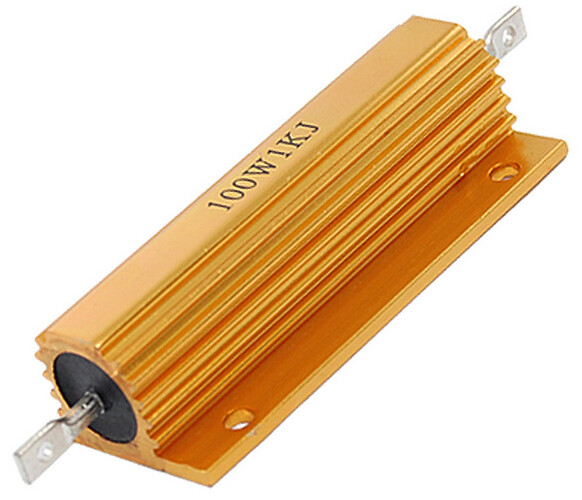
I was thinking I could use 3 of these 100w 1000ohm wirewound resistors in series:

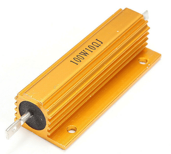
above a 100w 10ohm wirewound resistor:

I will use a laptop, i have several really old ones that I no longer use.

does my choice of resistors (wirewound 3x1000R / 10R for 120v should output 0.399v) sound correct to you?

Also you said sound card max input is 1v. So at 0.399v I am leaving myself a lot of headroom, possibly too much. What value should I be shooting for?

I was thinking even resistor rated for 10 watts should be more than enough, but the cost difference between the 10watt ones and these 100 watt ones is not that much. My thinking was that these ones would be less likely to fail or short, especially if I point a fan at them and keep them cool.

Thanks :slight_smile:

No. Why do you need so much current and hence to dissipate so much power? That’s overkill.

The “bottom” resistor in the chain wants to be 10 or more times smaller than the input impedance of your sound card. That’s likely to be not less than about 10 kΩ. So we’ll have a 1 kΩ resistor there. Let’s say you want 0.5 V rms across it, so the current in it will be 0.5 mA. Power dissipation is then 0.25 mW.

The “top” resistor will be passing the same 0.5 mA, and needs to drop 120 V (we’ll forget the 0.5 V - it represents a ½% error). The resistance value needs to be 240 kΩ. That’s very conveniently 2 × 120 kΩ resistors in series, but it wouldn’t make much difference if you had 3 × 82 k, or 4 × 62 kΩ. The total power dissipated in the ‘top’ resistor will be 60 mW. (30, 20 or 15 mW in each resistor.)

So you can use common 0.25 W or 0.33 W resistors with no problem.

More to the point, if you do touch anything other than the 120 V line, the current will hardly be enough to feel, let alone cause you any injury. (It might even not damage your laptop!)
With your 1 kΩ resistor, you could have 120 mA - that could kill you.

1 Like

Thank you Robert, that is scary! I was only focusing on the output voltage and not the output current. The good news is I think already have these resistors. I don’t have to order and wait for them to arrive.

Thank you very much for the info :slight_smile:

Don’t take this the wrong way, but I’d much prefer to scare you now than you find out the painful (hopefully), or worse, way.

1 Like

absolutely! I appreciate it.

edit: just finished rummaging through what I have for resistors, which is nowhere near as much as I thought. I just ordered a 3120 pcs pack https://www.ebay.com/itm/143244374343

Will be back at it once they arrive in 2-3 weeks :slight_smile:

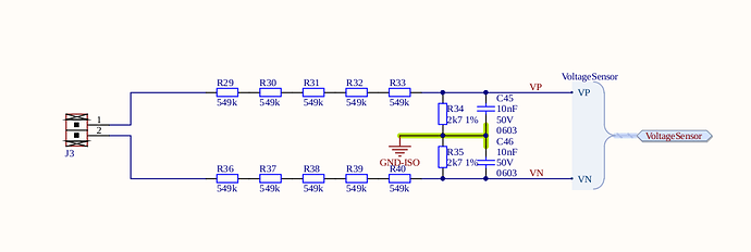
If you want to improve your odds against a mis-wired outlet/plug, you can treat both of them as equally scary with something like this:


That’s intended for the differential inputs of an energy IC, so you might need to tweak appropriately for your needs.

In the lab, when working on something with “dual supplies” you really need to be careful you’ve isolated everything before you dive in to probe/debug. A trap is to disconnect the USB (or PoE cable in my case) see all the LEDs go out and think it’s safe to pick up the board and start adding scope probes.

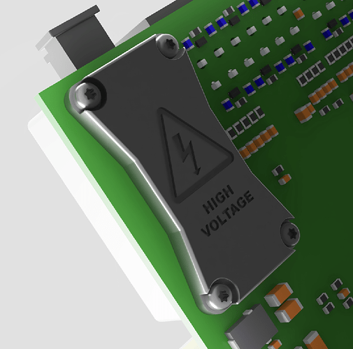
For additional security against concentration lapses, you can wrap both sides of the board around the divider network in a 3D printed safety cover: