newer wvc300 (8 character id) or older wvc300 (4 character id)
I tried both f22000024065fd0808f6 and f2024065fd0808f6.
But I have a new one with the ID 20000240. I would try to connect with the KD Monitoring, do anyone have a version für Win 10?
the software goes through the modem comport do you have a r3 modem… and it translate to be sent to the inverter
the key for that would be for the new r3 inverter from the doc i read
f2[-4bytes][-2bytes]00 00[4 byte]65
f2[modemid][powerid][adj][inverterid]65
f2 1a 2b 3c 4d 5e 6f 0000 12 34 56 78 65
directly by hc-12 not know yet.
I do not have a r3 inverter yet (coming) so I can not test any theories for the r3 directly
but i think it possibly one of the combination below considering the new info
f2[inverter]65 [modem] [power]
f2 12 34 56 78 65 1a 2b 3c 4d 5e 6f
or
f2[inverter]65 [power] [modem]
f2 12 34 56 78 65 5e 6f 1a 2b 3c 4d
or perhaps little endian of the sent
f2 12 34 56 78 65 4d 3c 2b 1a 6f 5e
f2 78 56 34 12 65 4d 3c 2b 1a 6f 5e
or simply reversed
f2 87 65 43 21 65 d4 c3 b2 a1 f6 e5
or some combination of that considering the info that was provided and how they tried to make it a bit difficult for the r2 modem by using little endian conversion
feel free to try to hit the the correct combination
Now i changed the HC12 in the Inverter and I am realy sure that the communication between the both HC12 works. But why i cannot get a respons from the WVC300. And the dc voltage is also connected. Hmmmmm. maybe its too late, maybe I have tomorrow mor luck.
This is now becoming a large post. As it keep growing, more and more will come to check it out. Also, it is really important to read most of the messages here, mainly the latest one.
You can’t and probably will not communicate yet. Our problem is that the message sent wireless is different from the modem. No one knows for sure how this message is built. We are all just guessing. @Stephen gave us some suggestions. I’ve tried all of them. I will test again later. Since you @Rene_Baars have a R3 modem, the best way is just keep trying to communicate with trial and error. @Anson_Guo gave us valuable information and he is helping us. I’m sure we will reach the result soon.
My guess is that the first 2 bytes are inverter (20 00 → 20 ff).
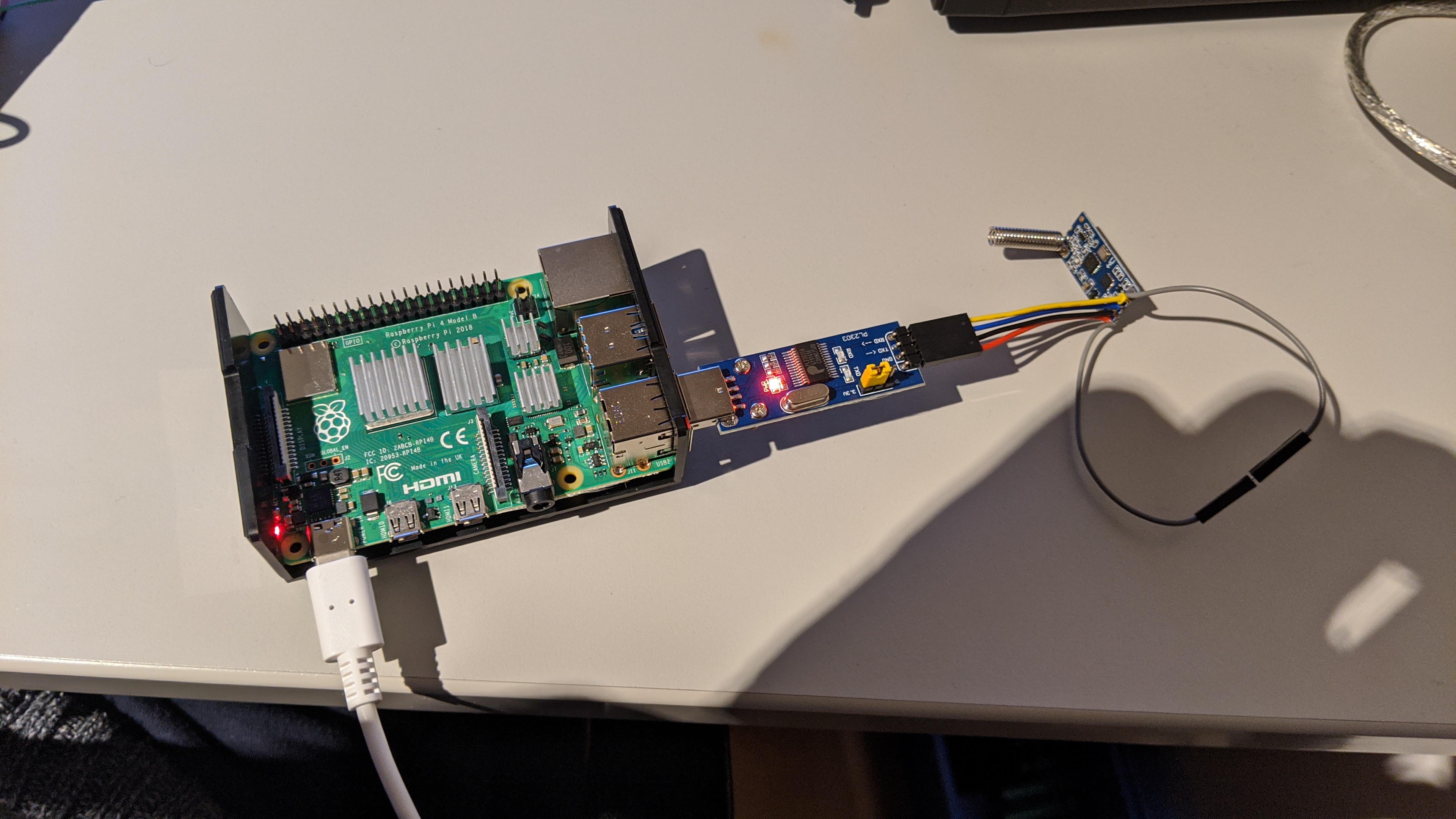
@Rene_Baars you can use uart pins (raspberry) for HC12.
So, now I have time the hole night to try every combination of bytes to get a communication. I have to use the USB to UART Adapter, because I need the UART on the PI for further Connections.
I will give you my results of my tries. 
Do anyone have a R3, a WVC-WIFI-Modem and a HC12? With the combination it should be easy to find the Right masage like @SuperNinja did.
curious now that you took out the original hc-12 what are it’s setting and if you hook it up to usb serial does it work for you talking to your other hc-12s…
I ask because there are two frequencies used on the r3 inverter 433mhz and 470mhz that are factory set 433mhz is for the r3 modem connections and the 470mhz is for the e-box connection – the reason I ask their might be completely different protocol for the 470mhz connections versus the 430mhz
I checked the configuration with the “HC12 configuration Utility”. It has the same Settings like the factory Settings.
- 9600 bps
- Parity = None
- StopBits = 1
- DataBits = 8
- Channel = 1
- 433,4 MHz
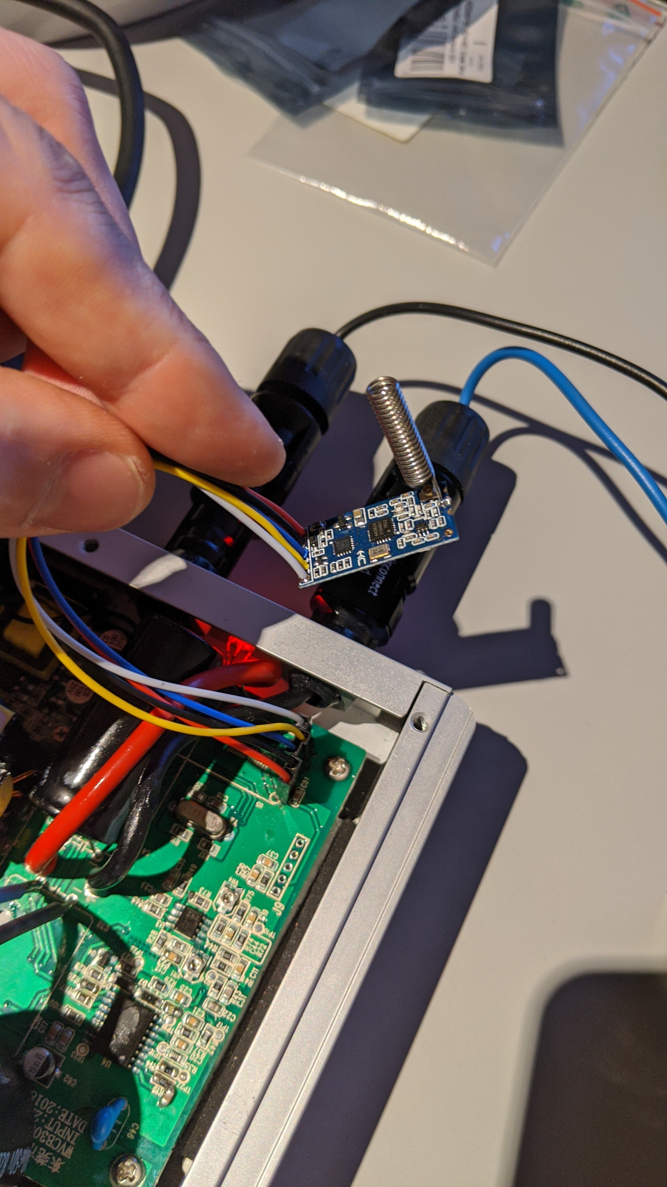
I made a connection between the “Inverter HC12” and a “new HC12”. I connected the RxD and the TxD from the “Inverter HC12” together. After this I sent a string over the “new HC12” to the “Inverter HC12” and I got an echo. So, the connection between the two HC12 works.
Do anyone know the respons for the F8 massage (Modem_Connection_Test) from the WIFI-modem to the KD Monitoring software?
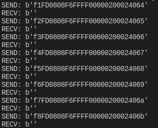
Try to bypass hc12. Check common voltage levels and directly connect Rx Tx to the inverter. It will speed up your tests. You can try my bruteforce script. Maybe you have better results than me.
Try
f5[inverterid]68
Replace f5:
F0 f1… Ff
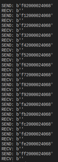
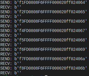
Try to replace 2000 by:
0200
02ff
20ff
you have to change the end byte to match-- this is the serial port connection via the wireless r3 modem - whether it is pass directly through or altered as in what the r2 modem does is unknown currently
Inverter command summary:
Inverter power is cleared--F0 FF FF FF FF FF FF 00 00 80 01 FF FF 00  The same return value
Power adjustment-----F1 FF FF FF FF FF FF 00 00 03 00 FF FF 01---64 The same return value
Data collection------F2 FF FF FF FF FF FF 00 00 03 00 FF FF 65 According to the above example
Boot control-----------F3 FF FF FF FF FF FF 00 00 03 00 FF FF 66 The same return value
Shutdown control-------F4 FF FF FF FF FF FF 00 00 03 00 FF FF 67 **The same return value
 Chart data-----------F5 FF FF FF FF FF FF 00 00 03 00 FF FF 68 Same as F2 Inverter
code writing-----F6 FF FF FF FF FF FF 00 00 03 00 FF FF 69 The same return value
Inverter code reading-----F7 FF FF FF FF FF FF 00 00 03 00 FF FF 6A The same return value
Inverter value adjustment-----F8 FF FF FF FF FF FF 00 00 03 00 FF FF 01---255 The same return value
though this makes me wonder if typo 03 00 FF FF should be FF FF FF FF inverter ID input according to the pdf or the stumbling block why no one getting reply maybe your inverter id of 20000240 should be 03000240
input format for the R3 modem:
fX[-4bytes][-2bytes]00 00[4 byte]6X
fX[modemid][powerid][adj][inverterid]6X
send format on hc12 Unknown
comparison to input format R2 modem:
fX[-4bytes][2byte]6X
fX[modemid][inverterid]6X
send format on hc12 Known
fX[inverter id] 6X [ modem id]
Ok, the PI is busy. At the moment the Inverter and the Pi are connected by wire.
Could you send me the mentioned pdf?
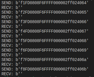
No luck…
in your first picture you look to have 1 to many “0”
edit: never mind you just shifted down the 2 placement