Workaround for the communication problems - change resistor in controller

I’m happy to read about the interference others also experience.

For me, I have computer dedicated for crypto mining close to the setup of hybrid inverter and battery.

When the inverters work at higher capacity the computer crashed…

I now have double fine maze chicken wire as grounded shield, that works.

The threaded rods I use to compress my cells got electrical charge also, enough for a nasty bite.

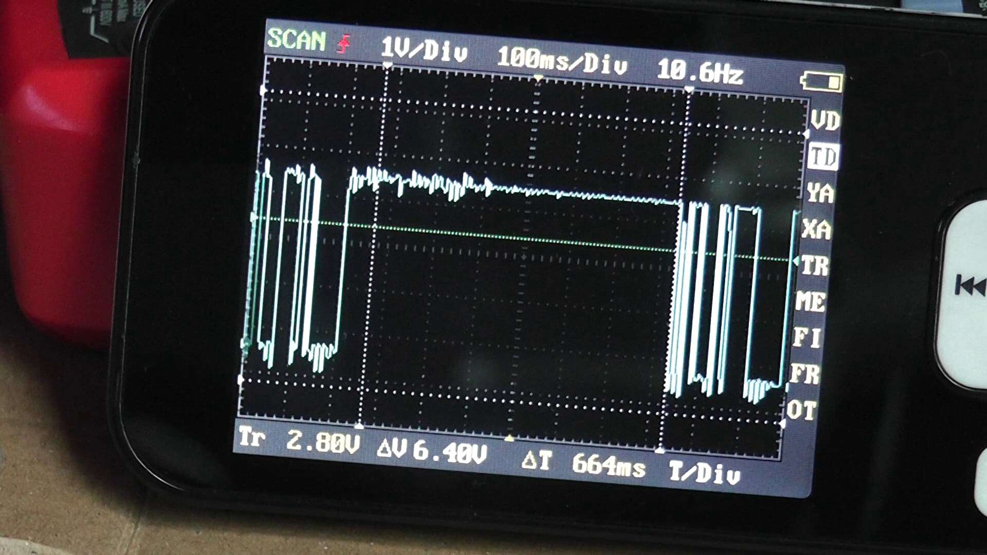
Safe to say, I have “noise”.

I’m not sure how to measure this, or place in calculations.

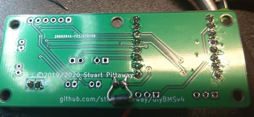
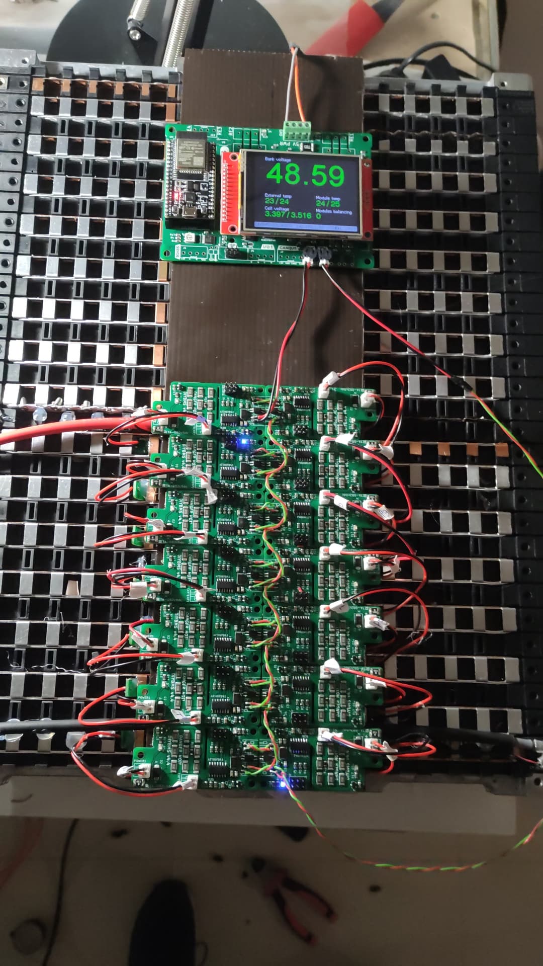
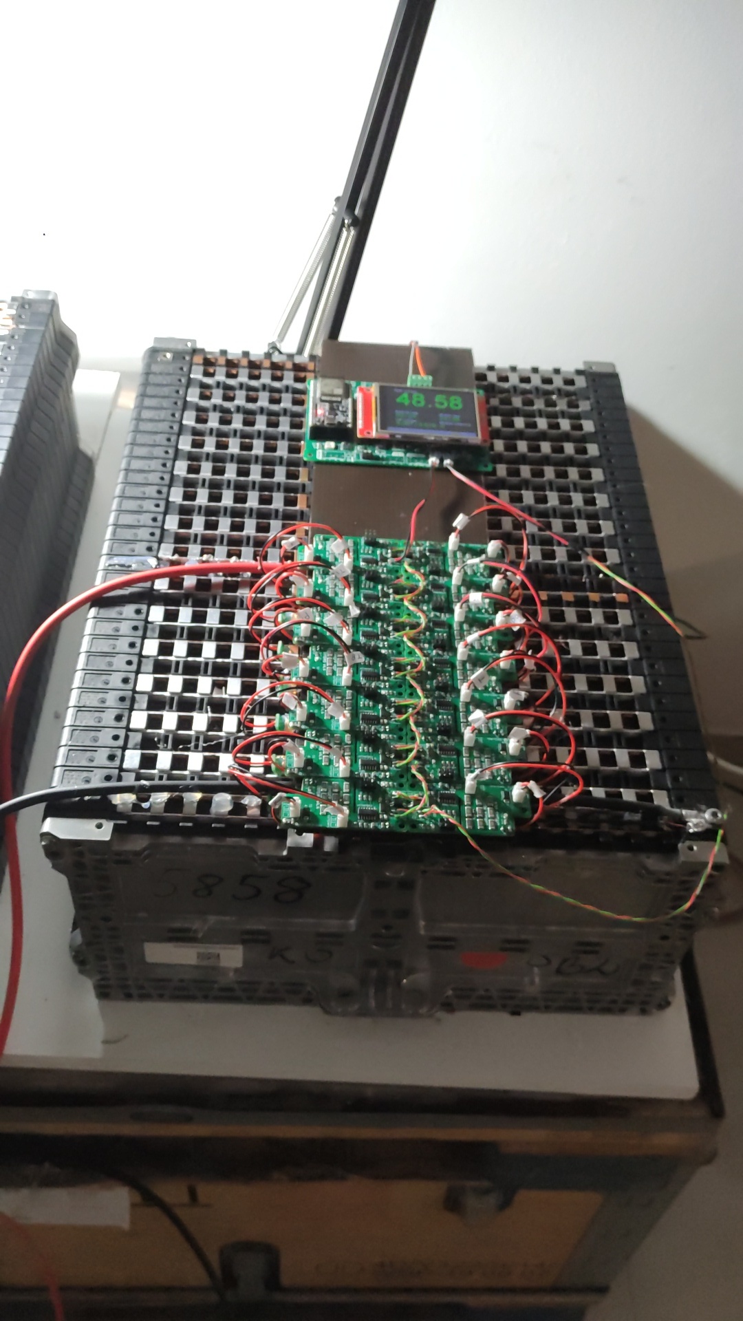
For the cell monitors, they will not be at the cells but close by, above the battery (2 layer).
I can make similar shielding between the cells and modules, if that makes sense.
It does require additional work, wire mesh on top of battery terminals will give nice fireworks, and contact at the bottom of the cell modiles will kill them quickly …

If it doesn’t make sense, I leave them “levitated” on pvc mesh, about 10-15 cm above the cells for heat dissipation.

Wire mess would be additional layer, with possible issues as described.

The computer problems, and now knowing it might be sensitive, I better prepare as good as possible.

Only if it makes sense to do so.

@fhorst1 Maybe a good start will be connecting all metal parts (Except the busbars :smiley: ) in your setup to ground. This makes not only your setup safer it will also make sure they are not being charged.

1 Like

@ Albert,

All parts that aren’t carrying current are grounded.
Include the threaded rods.
Without grounding, they got charged.

Grounding battery cables…
Doesn’t seem a good idea to me.
Perhaps shielding them, and ground the shield.

Would iron mesh be overkill to prevent/ reduce noise?

That is why I was saying ground them… I think if I was in your shoes I would first try to find what device is creating the noise. Batteries can’t create noise so a charger/inverter might be responsible. One of these would need shielding in some sort of way.

Have the rods broken through the plastic insulation of the cells? They should be completely isolated, otherwise you may start to get shorts across the battery or cell drainage.

for a long shielded cable (4/5mt) is it better to leave it as is or ground on the ecu end like they do in cars?

Hello Marc,

shield with grounding is mostly better.

thank you but ground where? To the cell , the module or to the controller

In this case i would prefer the ground of the Inverter (Case) If its grounded, because the ground of the Batterie is not always real ground.

grounded the shield but i lose com as soon as i start to charge

Now i understand why i can’t shield to the car.
I still get a wrong voltage reading when charging with long cables even if i lower the noise on the line.
i forgot i had a small osciloscope:

ALL charging at 20Ah

controller directly to rear pack 12s

controller to 32s with long cables (osci on the cell 8 to 9, 5 meters ±)

if i ground the 8-9 cable to the car

if i ground the 8-9 cable to cell 9 ground

Well I tried this fix I found on the issues
and it didn’t work for me. I’m pretty sure the diode is in correctly… But I think it made it worse! lol…
I’ll try the even lower R value or the inverter…

Well I tried the even lower R value and that seems to work.
Here is yesterday with the diode “fix”


The flat parts are where it loses communications.
Here is today with a 1.2K and a 1K in parallel.

much nicer!
I may try the inverter fix as well and put the R back to 2.2K

Good morning,

I’ll introduce myself first: I’m Portuguese and I’m enthusiastic about alternative energies and DIY. I have 3kW of photovoltaic production in my house for self-consumption and I recently added lead acid batteries to store the excess energy, 5kWh of usable capacity.
More recently I was able to purchase a used battery from an EV to replace lead batteries. Of course with lithium batteries I have to add a BMS for monitoring and security reasons. I’ve been following the diyBMS project for some time now, I’ve even followed Stuart Pittaway’s youtube channel, author of this excellent project, to whom I want to thank.
Following Stuart’s instructions, I ordered the manufacture of boards from JLCPCB for the modules (V4.40) and for the controller (esp32 branch V4.3).

After soldering the remaining components and doing some successful tests with only 2 modules, I decided to mount a matrix of 14 modules in a lithium battery section (li-ion) and put the controller to communicate with my Home Assistant via MQTT. I put some pictures here and I also have videos on youtube, if I can put the links here.
The system works fine for a few hours, but sporadically and without touching anything, the modules stop communicating with the controller, leaving all of them except the first one to flash twice quickly every 8 seconds. The 1st module always blinks only once (as it should be). I’ve reorganized the assembly of the 14 modules in order to shorten the communication wires and replace the controller’s resistance R2 by 300ohm. Still in trouble. I also replaced the 1st and 2nd module as well as others, but without success. For example yesterday it was working well for 11 hours having only momentary failures 3 times during the night and in the morning it stopped communicating at all around 8AM and never re-established communication. I turn off power to the controller (a power supply from a raspberry PI) and turn off power to the modules one by one. Unsuccessfully. Also already replaces the power supply, the failures continue. I have the lithium battery on a bench, it’s not connected to the inverter, and it’s away from it. During the 11 hours it was working well, the inverter went through all the operating phases, charging, discharging, standby… I don’t think it could be related to inverter noise.
I know that some problems and solutions for this problem have been reported here, I’ve tried to follow them all but I don’t know what to do anymore.

I ask for help here in the group, with any suggestions that might help me move towards solving the problem. Thank you very much!


Good job so far!

Normally I would now begin asking you to unplug and swap around the modules to narrow down the issue, but I see you have soldered the connection wires between the cells.

That’s going to make it difficult to resolve issues.

It’s an honor for me to be helped by you, thank you Stuart!

I soldered the communication lines because I had had communication problems in the previous setup, with longer wires and jst connectors. I decided to place it in such a way as to shorten the length of the wires as much as possible and also eliminate the possibility of bad contacts in the plugs. I also thought it was tidier, prettier. But really, when it comes to tracking down flaws, it’s harder.

I also thought that it might be a defect in the attinys’ welds, as I soldered by hand with a soldering iron without temperature regulation.

Since the 1st module only blinks once (as it should be) and the following ones blink 2 times fast, is this an indication that the problem may be with the 2nd module?

Anyway, I’m going to place the jst connectors and start all over again, then I’ll leave news here.

Thanks again!

Sergio

What should happen is you will see a traveling green light starting with the first module (unless the 4.4 modules are different??). Blue lights means no communications, I believe. If you don’t see the first green light then the first module isn’t getting anything from the controller. But if it was working, then you probably already know this…

If you see a module doing the double blink every 8 seconds it’s operating in standalone mode.

This means it’s not received any valid messages from the preceding module (or controller).

So definitely the first place to look if where the last good module is communicating with the controller. Follow the flash of led lights down the string.

1 Like

Yes thanks. I have version 4.40 for the modules, the leds are blue. One link means communication (one sequential blink in each module in the series), 2 rapid blinks means no communication, ie are in stand alone mode, as Stuart said. Thank you!

I’m currently making the cables with jst connectors (they’re plenty!) and soldering the connectors to the modules to redo the connections. I then report the results. Thanks!

1 Like