There will definately be differences, but I don’t know what they are. I would have expected the core power supply to the ESP8266 to be roughly the same between those two devices.
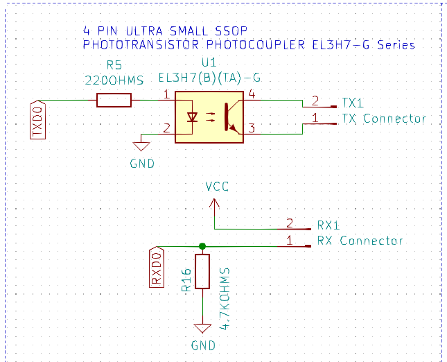
Hi @volkergi1970, If you look at the V4.21 or V4.40 of the modules R5 is the resistor which feeds the EL3H7 optocoupler - this is 220ohm already.
This should be feeding 10mA of current @ 4.2V cell voltage.
Part R4 is in the voltage divider
@stuart I programmed mine via the controller board so all settings and fuses should be ok. And really my modules are not working at voltages below 1.888v. For me no problem I did this test only to check if communication is working at low voltage and it is.
Thanks for trying this out Albert - very useful.
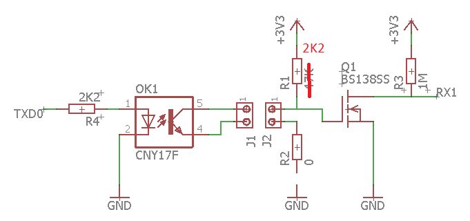
The R4 in your diagram should be 220 ohm if it emulates the existing module TX lines.
The MOSFET is purely there to invert the RX logic ?
Why do we not see issues with communications between the modules - it seems to only be the last connection back to the controller, is this down to the power supply to the ESP32 - as mentioned an isolated supply probably works best in these noisy environments.
Great, I don’t expect any need to operate below 2V, so as long as we keep that lower limit, I’m happy.
Stuart, for this test, I used the same one, a non-insulated power supply for the contollers. Esp8266 Lolin mini pro works better than wemos d1 mini pro.
The R4 in your diagram should be 220 ohm if it emulates the existing module TX lines.
My mistake the resistor on TX side stay’s as original.
The MOSFET is purely there to invert the RX logic ?
Yes it only works as an inverter
Why do we not see issues with communications between the modules - it seems to only be the last connection back to the controller
It looks to me the ATTINY is not very sensitive on the IO ports. and the cables between modules I expect to be shorter in most cases. In the original design the RX data line was at 2K2 from ground so there could be voltages on this line being seen as 1 or 0 by the ESP. I also see we are not using any of the pull-up or pull-down resistors in the ESP32 so basically MODULE_RX1 is floating. In my mod it is tight to 3v3 via a 1M resistor we can take this out if the 45K internal pull-up resistor of the ESP32 is used.
I’m powering my controller via a external 230v to 5V supply. People who power the controller from the battery via a DCDC converter might see more disturbance if connected charger’s or loads are connected. This is due to the rapidly switching electronics in these device they create small voltage peaks on both the positive and negative cables. with most DCDC converters GND is directly connected to the controller these peaks can easy reach MODULE_RX1 via the 2K2 resistor.
Now we can also go back to why the modules are not effected by this issue, only the first module is directly connected to GND as I said before I expect the ATTINY is not to sensitive on it’s IO ports or what i did not check maybe the internal pull-up resistors are active.
1M resistor is quite a weak pull up - is this just to reduce the current draw?
I’m happy to re-work the existing controller board if it helps reduce comms errors - adding a couple of resistors and a low price mosfet won’t any problems and there is room on the PCB.
1M resistor is quite a weak pull up - is this just to reduce the current draw?
The resistor is at 1M to keep current low, I think a MOSFET can switch faster also if the current is low. But maybe a pull-up matching the pull-up of the ESP32 is better. in that case we come around 47K.
Before making a permanent change to the PCB I think it is better to wait for a few people to test the mod @volkergi1970 was willing to test it on his noisy setup. I’m still waiting for parts before I can test on my setup don’t know if it is noisy in the base but I have enough equipment to make at a broad spectrum of frequencies.
btw Why did you choose to use software UART instead of HW? the HW pins are not used now.
I am using HW - the pins on the ESP32 can be configured via the hardware multiplexer.
1 Like
My test setup obviously isn’t noisy!
800,000+ packets through and not a single loss - the cells are way out of balance though!
1 Like
Oke this morning I managed to get some disturbance on the communication between last module and controller. What I did was placing a DC motor with brushes close to the wires and make it run. This was on the board with the modification. This evening I will change the pull-up resistor R1 to 2K2 that will make the data line more solid 3V3. If that is not satisfying R3 is the next resistor to change. It might also be disturbance is entering the system by the supply of the controller. Decoupling of the 3v3 is looking good to me I’m only missing it on the fused 5V circuit so might we useful to see what is happening on the 5V supply.
The 5V rail is dependant on the quality of the power supply the end user has picked.
I couldn’t do much with the design of that part as I don’t know what the end users battery voltages are, could be 12V, 24V, 48V or higher etc.
@stuart in my setup the controller will get its supply from an external source. I want to have the controller running even when main battery fuse is blown.
@Albert I did a quick modification to the controller circuit based on your design - screenshot below.
Does this resemble what you have built?
How’s the testing going?
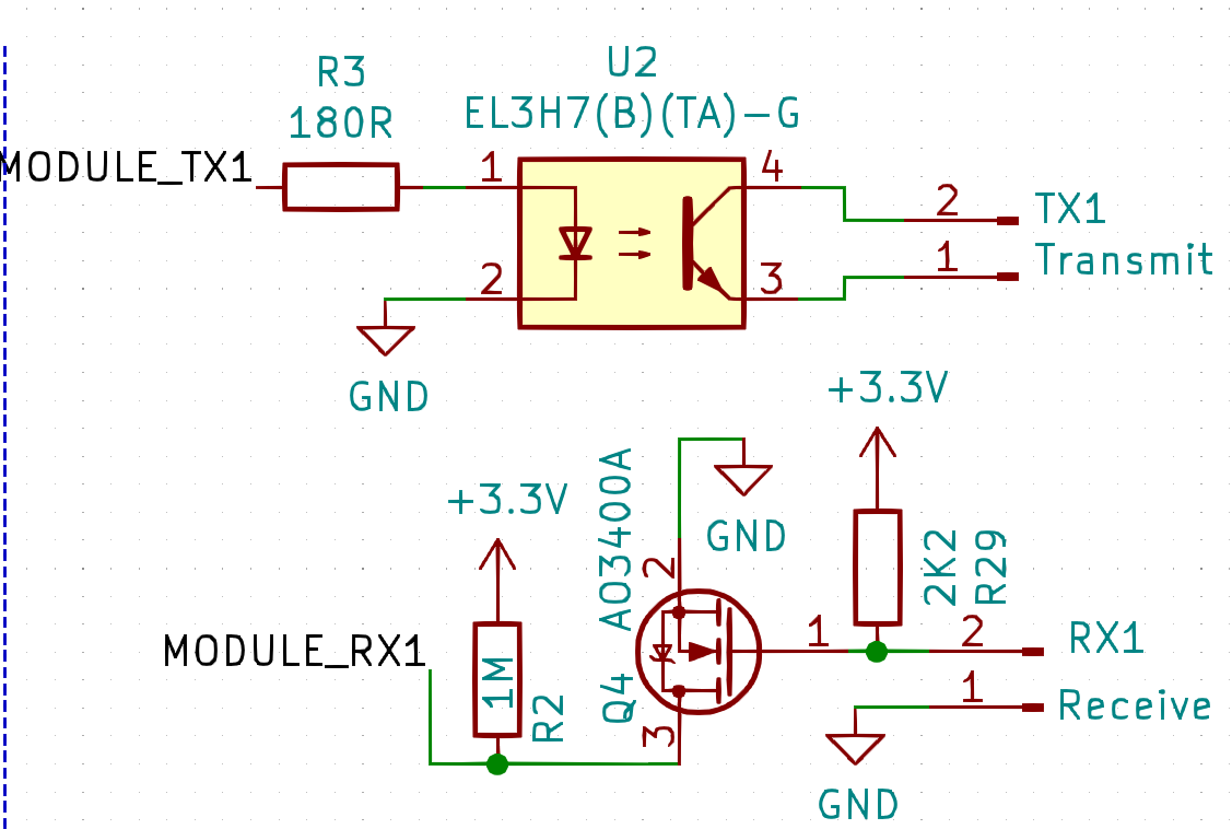
@stuart Yes correct this is what I have done. Last thing I changed was R29 from 47K to 2K2 That is now running from yesterday evening on till now without any error even with the motor with brushes (sparking all over the place) in between the wires. I’m still hoping @volkergi1970 is also testing this mod as I’m curious if in his situation it also helps.
I have read this thread with interest as I am about to build my first controller and it too will be in a noisy EMI environment.
Sorry up front on the terseness of this message and not first checking in lab but I’m really restricted for time at present.
While the proposed changes may help with the issue – I am not sure it is addressing the real issue.
I am still waiting on my parts to arrive from LCSC so I can test but I thought it best to call it out prior to users modifying their Controller boards.
To me the Opto Couplers on the monitoring modules are being under driven. In fact based on the very confusing vendor spec sheets (is to me ) it may be lucky to be turned on at all especially at voltage extremes and extremes of tolerances of opto couplers. And EMI loves this.
Some extremely rough calculations before any mods to Controller or Monitor Module circuits.
Note some loose assumptions to make conversation easier.
Module_RX1 input to ESP32 needs to swing from 0V to 3.3v
3.3V across R2 of 2k2 so it needs 1.5mA minimum for full voltage swing.
Now let’s take a look at the Opto Coupler at cell monitoring.
It has potentially 3.65v drive the led via 2k2 R5.
Potentially at full charge 3.65-1.6/2k2 = 0.9mA
If we look at the spec sheet for the opto coupler – figure 2 initially.
(capital eye->) If of 0.9mA will give us a normalized Ic of around 0.09.
If we now look at the CTR maybe normalized of 0.4*
Both indicating we are not driving the opto strong enough to get anywhere near full voltage swing.
A quick comparison of R5 (2k2) Monitoring Cell versus R3 (180) Controller would confirm there is an apparent issue. To me these are meant to be equivalent mirror electrical images of each other yet have a ratio of 12:1.
To me it might worth investigating changing R5 inline with R3 or even better a revaluated optimum value.
Final thoughts changing a resistor on each module is much easier for us especially if it works. It might also explain why some mention having inter module comms issues as well. If the theory is correct comms issues could appear in all links except the Tx from Controller to first Cell Monitoring module.
Thoughts ?
Are we getting a bit mixed up here?
This is the V4.40 circuit, the optoisolator is driven by a 220 OHM resistor (not 2K2) - I make that about 10mA driving current - this obviously varies across the 2.0 to 4.5V range that the cell could be at.
Stuart, All,
Sorry I really need to get my eyes tested.
I miss read the 0 and O and thus went down a bad rabbit warren.
So don’t waste further time on my suggestions due to a basic miss read.
Mick
1 Like
No problem Mick I even made the mistake and have put 2K2 in my proposal diagram. 
1 Like