Better is a Switch to GND without a Resistor R3, so the EM Impulse have no Chance when the Optocoupler is high at the Input. If it is Low at Input and high at Output EM Impulse has no effect, because the RX Input is already high.
If I was starting over again, I’d do this, but it isn’t going to help the existing devices/users.
@volkergi1970 what i proposed was making data line input high via R2, it is at 3v3 so emi can not raise it. When the optocoupler closes the data line is pulled low enough for the ESP32 to detect a 0 instead of a 1. The emi is never able to pull module_rx line to low. As stuart is saying if he could start over he would have chosen this approach I think wise. Well I think without a change of the software it is possible to implement this for current users who have communication difficulties, then only a little amount of people have to do a modification to the controller board.
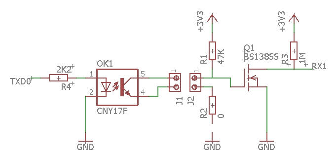
Not modifying the software makes the mod to the board a little bit harder placing a inverter in between R2 and the ESP32 is solving the issue of software change. The easiest way to create an inverter is using a mosfet with a 1M resistor that pulls drain up gate can be driven with the signal coming from R2. The signal on drain will be the inverted signal of R2. In that case we also do not need R3 anymore.
Cuting 2 traces adding a few resistors and a mosfet will do the trick.
I can easily do the mod on the board for testing if communication is then working. Testing disturbance I can’t as I have no issues.
The esp32 supports inverted serial data, in code, but this would also invert the transmission.
@stuart tomorrow morning I will try if it works.
I had a lot errors, but I changed the previous power supply by isolated one and the errors decreased a lot. Try with a smartphone charger, you will see better reaults, and if it works, get a isolated power supply.
This maybe an very Important thing. My little Inverter for the 5V to the Controller, is a step down from the 48V battery without isolated Voltage. I have Filters behind, but the GND of the 5V Inverter is Connect to the GND of the Battery, and this in turn is connected with the noisy GND of the PV Inverter. It is possible that an galvanically isolated Power supply unit solve the problem also.
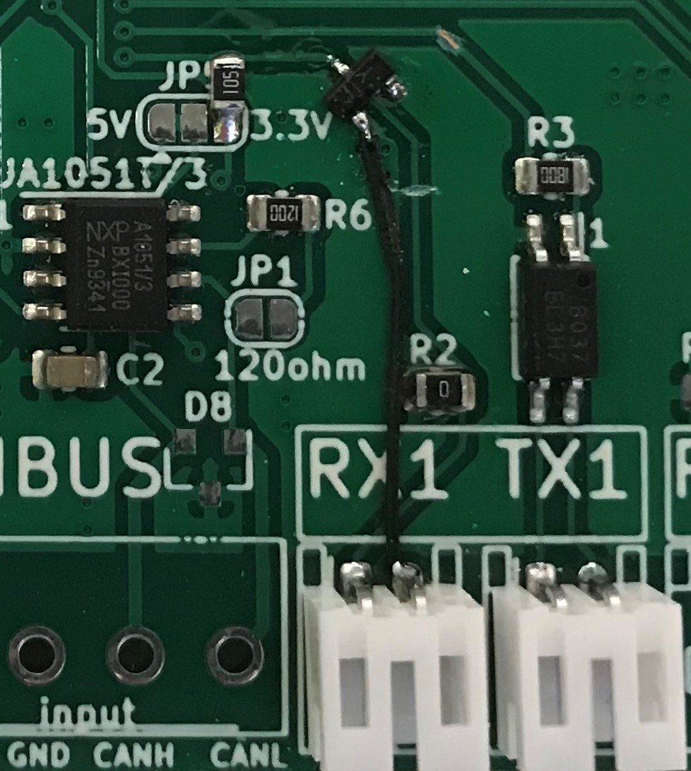
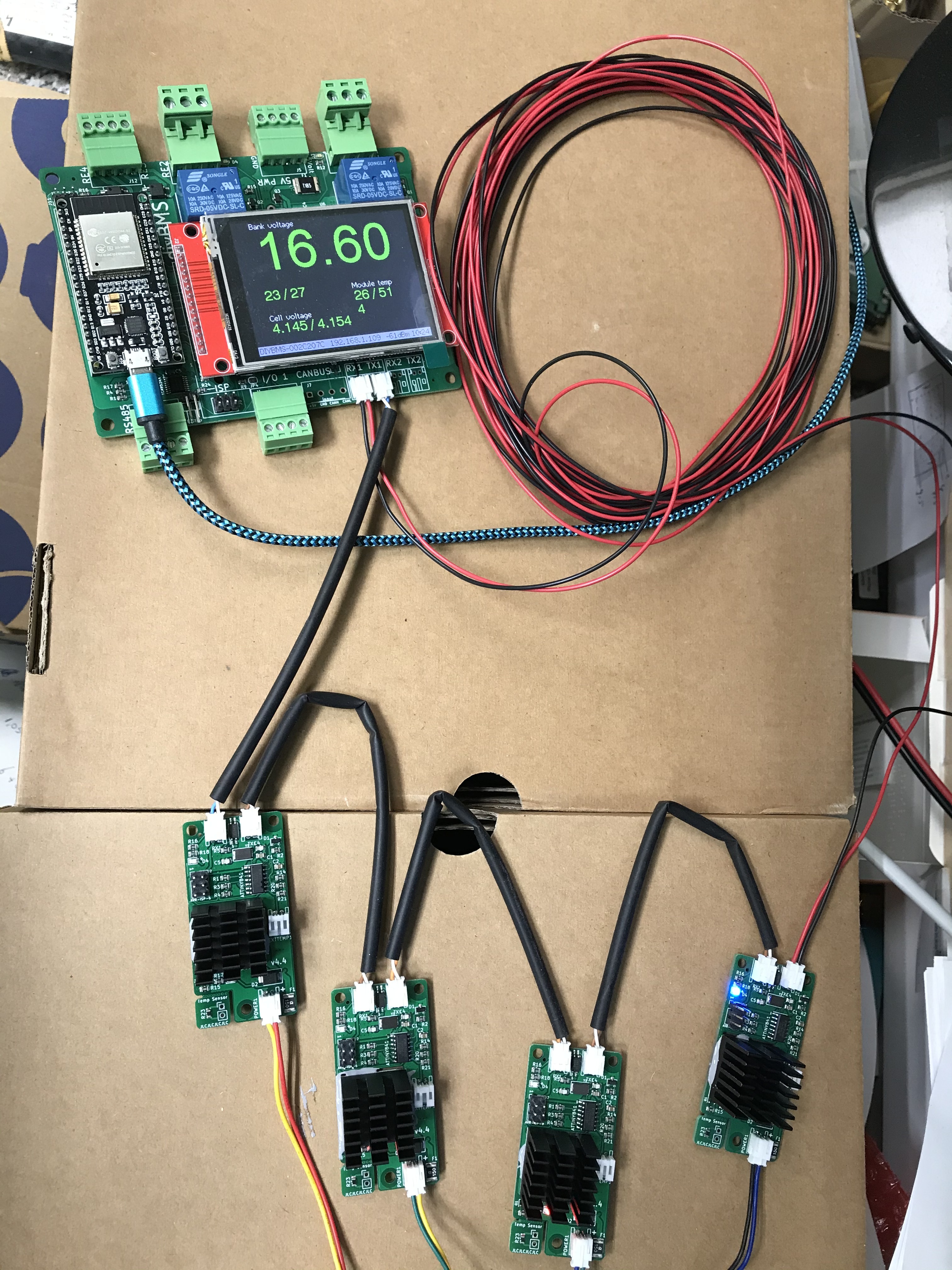
As promised I made a small mod to the PCB took the worst possible cable to connect the last module to RX and have it running on my desk now. Until now I don’t see any problems. But as mentioned before I did not before while using very short cables. I used the first MOSFET I could find BSS138SS but you can also use for example the AO3400A used at the modules to switch on and off the dump_load.
I Cannot See the benefit of this circuit, because the EMI Impulse on the RX Wire can also Switch the Mosfet, just like the Input of the Controller, If the Optocoupler in the last Module is open.
If you look just a bit closer the RX wire is pulled up to 3v3 so it can never be pulled down by EMI. When it is pulled down by the optocoupler it can not go up as it is pulled to GND.
Instead of a RX wire that is floating in between GND and nothing it is now GND or 3v3
Worst case with this circuit you can use coaxial or shielded cable so EMI has no chance on the RX line.
OK, now i see that you use the Mosfet only to convert the Signal. In Future Versions, the RX Input of the Controller can direkt go to R1 without R3 and Q3, and the Data must convert per Software.
@volkergi1970 to keep the software backwards compatible @stuart can also choose to add Q3 in a updated design. But first it would be good that someone test this solution that is now experiencing difficulties with communication.
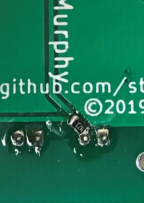
By the way i found, that R4 on the Cell Moduls is too large generally. If we Check the datasheet of the Optocoupler, we need at least 5mA through the Input Diode in the Optocoupler. The Resistor must U= 3,3V-1,2V Diode =2V/0,005A=400 Ohm. I would prefer 470 Ohm. This also reduces the EMI Sensitivity because of Switch the Optocoupler lower resistance to Ground.
Because I have a noisy Setup and measerement Equipment, i can Check the modified circuit.
@volkergi1970 Would be very good if you can test the modification. The resistor you are right, if you want to have a Collector current of 1mA trough the optocoupler. We only need 0.07mA when using a 47K resistor in my mod. Look at fig2 in the datasheet. We need a collector current of 3v3/47k=0.07 mA to switch, the forward current IF can be anything above 0.5mA at 1V2 so for 1mA a resistor of 2/0.0005= 4K should be sufficient. But if later on we find during testing that the resistor of 47K is to large we also have to adjust the resistor on the modules if the current to switch the RX line exceeds 1mA
Don’t forget to check the current across the whole voltage range of a typical lithium cell and also the extreme cases, probably 1.8V to 4.5V
If we calculate a Module Supply Voltage of 1,8V the R4 Resistor is much too high, because we have only a difference of 1,8V - 1,2V (Optocoupler Diode)= 0,6V for the Current through R4. 0,6V/0,0005A =1200 Ohm
I have just checked with my setup. The module is working till voltage goes below 1.888v (at that point I don’t see the ATTiny come out of sleep) if I bring voltage up from 1.5v the module starts to work again at 1.963v.
I have the ATTINY841-U according to its data sheet at 10 MHz the lowest operating voltage is 2.7v at 4MHz is is 1.8v so I think we have to be happy in our 8MHz setup it is starting to work at 1.963v
Hello Stuart, I use the esp8266 version and I don’t know if it is fortuity, but today I only change the wemos d1 mini by the esp8266 lolin mini pro and the errors decreased a lot. Do you think it is possible? Do these models use different circuitry? Thanks for your brilliant job.
The modules should be running at 2Mhz. The fuses configure the ATTINY for 1Mhz boot up, and the software switches to 2Mhz on setup() - in the “SetPrescaler” function.
B.O.D should be enabled as well
1 Like