Crud!! It didn’t really fix it. I’m still getting tons of lost packets not getting back to the controller.
IF I hold the cable (from the last battery module to the controller RX) in my hand they all get through. When I let go I can see a lot don’t make it. So still some EMC issue going on…
@jbuszkie can you try to use a pair of twisted network cable (if you cant connect these wire to the JST connectors just twist your existing wires), wrap it together with a bare wire in aluminum foil and connect that additional wire to ground on the controller board. If that doesn’t do the trick turn the cable around and connect the wire to the ground of the module.
DO NOT!!! connect to ground on both sides.
This might help or make it worse if the foil starts to act as antenna.
An other attempt you can try is on the controller connect both connections of RX with caps to ground. I would start with small capacitors 22pF and if needed bigger up to max 10nF this way you can short high frequencies. Only need to be carefull not to short the signal.
@Albert I already tried twisting them… I’ll try these other things as well… It’s certainly better with the resistor fix… But I’ll some of these others tomorrow…
One last thing that might help change the length of this cable for example increase with 1 third of it length this will change the wavelength and might eliminate the pickup of interference at a specific frequencie.
Can you route the cables away from the battery terminals and inverter? Thats where all the noise comes from. Also make sure you are using twisted cables (undo the JST cables and twist those).
@stuart I did twist the cables already. And the cables are already behind the main battery terminals… But I can separate them more. The noise, I believe, is coming from my mppt charger.
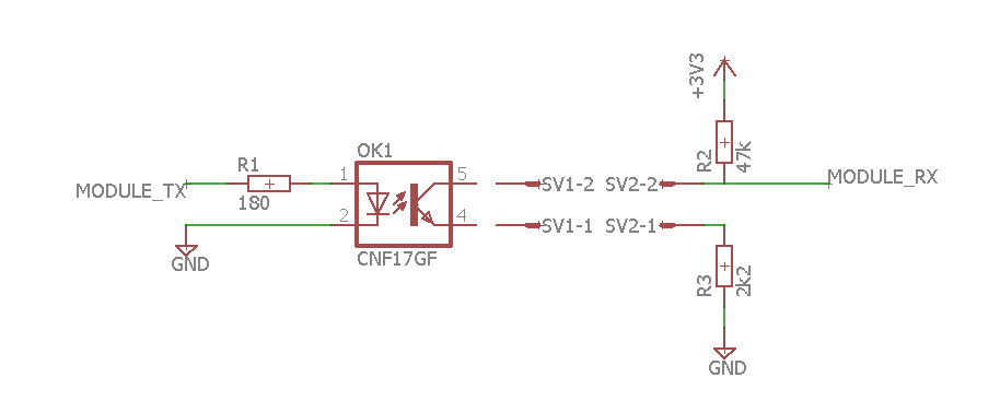
Because of your problem i have checked the diagram again, and measure the Signal on the Receive Input of the Controller. If my Inverter is in maximum Load, i have many Spikes on the Input and i also have sometimes lost Packets. Because it was only Sometimes it doesnt bother me. Now i reduced the impedances of R2 again, with the result of less lost packets. You can reduce the resistor R2 down to 220 Ohm without negative Impact of function, If you have a very noisy Setup.
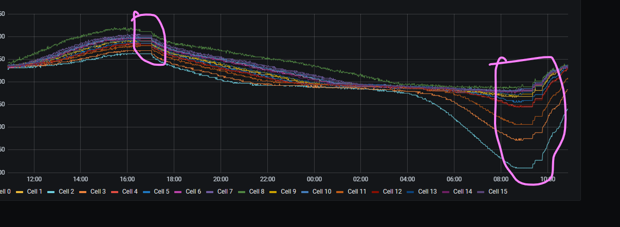
It’s better than it was. I’ll still play with the location and I’ll put EMI chokes on the leads coming from the charger. I’ll get those in a couple days. I’ll have to put a scope on it and see if the chokes make a difference… Right now it seems like my controller is creating the most noise when the sun first comes up and then starts to set…
Because of the Problems of Users Here, i have tried a test with R2 modified down to 220 Ohm. It shows a signifikant better Signal in my Setup. The Errors go down again from 10% to 0,3%. The modification from 4k7 to 2k2 was OK for my Setup, but I think it maybe a good Idea to Change the BOM again to 220 Ohms for a good Signal in all Setups.
How about the extended current draw by using such a low value?
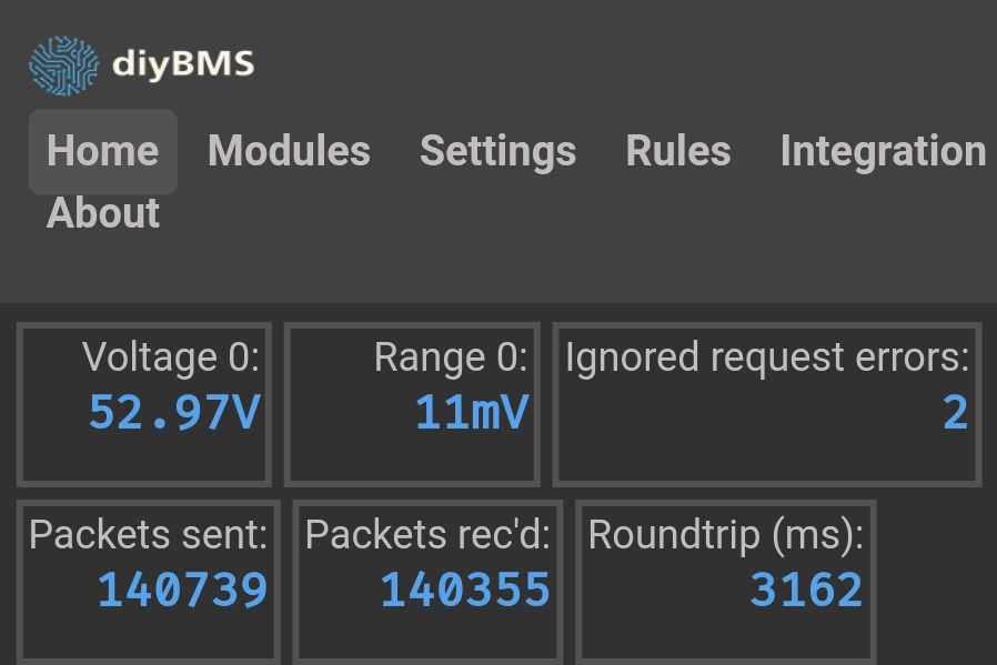
I’ve got a setup on my desk which has just gone past 600,000 successful packets of data, with no errors, and still using the 4.7k original resistor.
The Comms issues largely seem to vary with how good the electrical shielding is in each install and also what type of power supply is used to power the controller.
The current with 220 Ohm is 15mA in the Moment of a Data Impulse. Over the time maybe 5mA. Most of Power Inverter produce many electromagnetic noise. If the Inverter have additional an MPP PV Unit, the interference maybe stronger. My 5V Power unit for the Controller have a very Low ripple. The measered noise is only produced by the Inverter.
Isn’t that going to cause an in balance on the last cell in the chain? You will be pulling more current (I know its small) but all the same - could cause an in balance in the cell.
As the issues seem to be related to the controller receiving the last packet of data - how about some EMI shielding on the controller board instead?
Why not change to this way. Instead of modulate data on virtual GND modulate it on pulled up 3V3. This way interference via GND from charge controllers or loads is gone completely. The signal on pin 2 will be 3v3 or 0v14 I think that will be enough for the ESP32 to see a clear 0 or 1
In addition if this still result in interferance there is a possibility to change to thin coaxial cable.
The current through R2 comes from the 3.3V of the controller, and not from the last Module. Shielding the Controller ist not helpful, because the EMI comes over the data cable.