This is fixed in the next release.
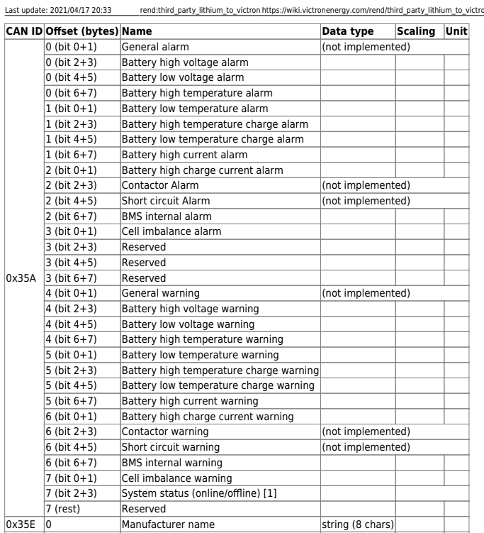
Data byte zero (in message 0x35a) on Victron controls the over voltage alarm.
These two bits are set based on the BankOverVoltage or CurrentMonitorOverVoltage rules.
If either rule has “triggered” (green on the web page) then BIT 2 is set to 1 (decimal 4), if the alarm is NOT triggered, bit 3 is set to 1 (decimal 8).
Now, I’ve also written a comment in the code
  // These constants are actually bit swapped compared to the notes above
  // as the Victron kit uses little-endian ordering when transmitting on CANBUS
so it could be that Victron has BIT-swapped to correct this fault in the documentation?
just wanted to share the feedback here as well.
After analyzing the issue more I found the root cause in a faulty translation (german).
I opened a new issue, see here for details:
I am currently testing the controller v4.4.3 and it is already a big improvement in terms of Victron integration.
However, I think the charging algorithm needs to be adjusted:
Let me summarize the current state (please correct me if I am wrong):
The DIYBMS charges the battery with a customizable current/voltage curve up to the “Charge target cell maximum voltage” value which is then maintained depending on the available charging power.
However, this is not an optimal solution for how LiFePo4 batteries should be charged. A very good post that explains the problem very well can be found here:
In short, the problem is that the battery should not be kept constantly at e.g. 3.5V, but charged and balanced to 3.5V and then discharged again to e.g. 3.33V. Keeping the battery permanently at 3.5V will damage the cells. (please read the link to this topic).
Victron has integrated this charging algorithm in its MPPTs, but unfortunately this is completely deactivated by activating DVCC and the DIYBMS takes control. So the charging algorithm implemented by Victron should also be integrated in the DIYBMS!
What is your opinion on this?
As soon as you have DVCC activated the Multiplus shows “ext. control”
To solve both issues, maybe not transmitting CVL, CCL abd DCL will activate Victrons controls and also lets the Multiplus decide itself wich operation mode is prefferable.
but i dont know if that works…
The problem here is that the job of a BMS is to tell the system what it can do without damaging the batteries, and that does include charging to 3.5V. Anything else is not. Telling the Victron code to actively discharge simply doesn’t work, all you’re going to get is an overvoltage error when you reduce the max voltage too far below its current level.
If the Victron control loop doesn’t do what you want (why not? you can set a target SoC, if I remember correctly), ask them to fix that, or switch to External Control and do it yourself, with node-red or Python or whatever.
But please don’t overload BMS code with “features” that don’t belong there.
Morning,
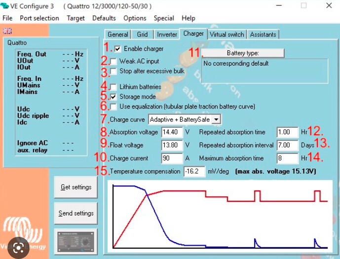
You are correct @buddhafragt. Not sure what inverter/charger your using but Im using Multiplus 2 and if you connect to your inverter charger using victron connect you can set your absorbtion and Float voltage. Set your Charge curve to fixed.
@Smurfix is right. Use the venus OS Large image with node red set the ESS to external control and write all your algorithms yourself. You could easily write a flow in node red to do this. I do something very similar ![]()
Its the BMS’s job really to tell when to tell the inverter/charger when to change from CC/CV, absorbtion, float modes.
Need any help with Node ned flows. Were all here to help ![]()
Cheers
Gareth
All that absorption/float/whatever stuff is necessary for squeezing the most charge out of lead acid batteries, but LiFePo4 cells are way different and with them these words don’t really mean anything. LiFePo4 cells do not “absorbe” or “float”. They require balancing instead. You can’t fix overloading an unbalanced stack with a charge curve.
Instead of this, it’s the BMS’s job to reduce the max voltage when the stack is unbalanced and one of the cells is about to exceed its max voltage; the problem is that most of them don’t do that.
I wrote some code for dbus-serialbattery to work around this problem, see Add dynamic voltage adaption by smurfix · Pull Request #513 · Louisvdw/dbus-serialbattery · GitHub
@gjones84 I am using MPPT SmartSolar Charge Controllers and the setup is similar to the Multiplus… but all settings are ignored when DVCC is on.
1 Like
please read the post quoted above, then you will know where the problem lies.
@buddhafragt maybe this will help?

I think, @buddhafragt has a point.
But it might be easier to let the Cerbo and the other Victron equipment do its things.
- The DVCC will take control of the “do not exceed” CVL, CCL and DCL, set in the Cerbo GX (or Venus OS)
- The MPPT’s, Multiplus or other Victron equipment will run their charge cycle (as usually) with their internal charge settings.
- The diybms only interference if there is a cell balancing or a warning/error and interupts, limits the victron system
there is no need for the diybms to dictate the CVL, CCL or DCL if there is not emergency.
LiFePo4 batteries get out of balance all by themselves, and short of regularly (and reasonably slowly) charging them to max voltage, thus letting the BMS’s balancer do its thing, there’s nothing you can do about that.
But “reasonably slowly” depends on how badly out of balance the battery is, and that in turn depends on the individual cell voltages, which only the BMS knows about. Thus the BMS should adapt the max voltage to whatever the cells are currently doing. (Same for minimum voltage.)
Let me give you an example here. If you have 16 cells at 3.4V and your “soft” limit is 3.5V, then 56V (16*3.5V) is a reasonable CVL to set. However, if one cell already is at 3.5V and all the others are at 3.4, charging to 56V means that you end up with 15 cells at 3.41V (at best), one at 3.65V, and a BMS that disconnects the battery pack – at 54.8V. A reasonable BMS should know about LiFePo4 charge curces, notice this imbalance, and set the CVL to 54.5V until its balancer circuit gets around to discharging the 3.5V cell.
The fact that most BMSes don’t yet(??) do this is the problem here. Charge curves in inverters are a badly-performing workaround at best – and at worst they can’t prevent cell over/undervoltage.
Bottom line: yes there definitely is a need for the BMS to continuously dictate the CVL/DVL, and not just in an “emergency”.
1 Like
Gareth, so all your charge settings you make in your Multiplus working with DVCC on?
Following your comment, i have installed the new SW on the controller.
Well it runs pretty smooth with the new dynamic regulation. Pretty cool. Now i agree with you.
my comments were regarding the old SW version.
Hi yes DVCC works a treat.
DvCC is a register you can also wrote to via mqtt and modbus tcp.
Maybe it is more clear, what we need in the DIYBMS if you read this thread in from the Victron community:
https://community.victronenergy.com/questions/127476/new-useful-dvcc-function-switching-to-float-voltag.html
I fully understand what you want to do now.
Option 1 would be to either upgrade the firmware in the BMS somehow. It would need to to look at the VEBus State and when in absorbtion for x amount of time the CVL is reduced to a preset value. Ive not seen this in any of the JKBMS, Batrium bms. Not saying it cant be done but that would need stuarts input.
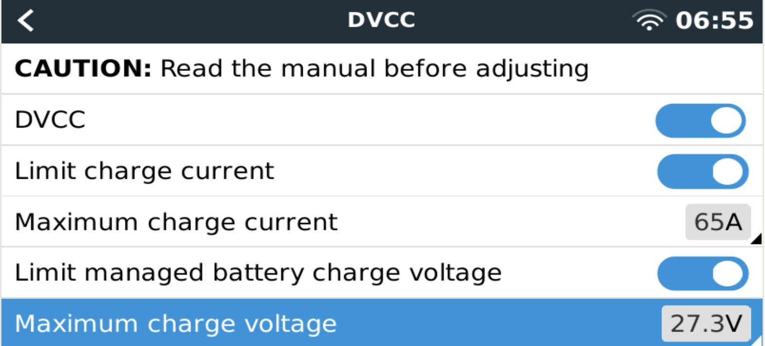
Option 2. Have you tried charging your pack to Absortion. Leave it there for say 1 hours then reduce the max charge voltage in the dvcc page?
If so. This is something you could easily do in node red. For example in my case
Phase one- charge bulk 27.3V 3.4125per cell (8S)
Phase two- hold in absorbtion for 1 hour.
Phase three- write command via mqtt to dvcc max chargevoltage 3.3 x 8= 26.4V. Soc =100%
Reset 27.3V at 99% soc.
How does that sound?
I think, option 2 will work. But I just don’t have much confidence in Node Red, it tends to crash on me and for such a sensitive function, I would prefer a different solution.
To upgrade BMS firmware should be not too difficult, if the current sensor reset the SOC, the CLV is reducing. Then a re-bulk voltage offset from where the charging cycle starts again.
Maybe switch off DVCC and let the MPPT solar charge controller do the work. That will do float functiuon your looking for.
And for a bit of protection add a shunt trip to your DC breaker and program relay R1 so if voltage goes above 3.65 it trips it out.
Give your cells a good top balance before hand.
Cant help you with the firmware im afraid.