I think I’ll be happy with just two closely-matched probes, rather than absolute accuracy…
In that case just put them next to each other in a room, wait half an hour and measure.
Absolute value would matter if swapping with someone else though.
I filled my silicone collapsible coffee cup (silicone is a decent insulator) with ice cubes, then filled it with cold water from a bottle I keep in the fridge, then left it about half an hour. My IR thermometer recorded the water as 0.7°C and the surface of a melting ice cubes as 0.0. Probably the ice couldn’t quite bring the water down nearer to zero.
I reckon this is the best way to get a reproducible temperature. Any cup or mug would do as the melting ice should hold the water at a constant temperature for some time (the latent heat of fusion effect, iirc).
It took at least five minutes for the sensor to stabilise once in the water (I floated them between ice cubes).
On my multimeter I needed to change the range from 20 kΩ to 200 kΩ after putting them in ice water; there was a moment when I thought putting one in water had broken it ![]() .
.
From my experience at the NPL, calibration at 0 °C should used crushed, wet ice, like in a slush machine. It should look grey rather than white. Put the sensors in plastic bags and immerse the leads in the ice.
Check results by repeated measurements. For an amateur it’s possible to get an uncertainty around 0.1 °C.
It’s a surprisingly difficult measurement to make!
I found that as well. Good point on using slush ice, I’ll remember that for the next time. The plastic bags sure will complicate matters I guess. I only used this method for waterproof sensors before and just completely immersed them.
From your description the sensor is not a PRT but a negative temperature coefficient thermistor.
There are standards for inferring temperature from resistance with PRTs with uncertainty at a level of 0.01 °C or better, but there is no agreed formula for inferring the temperature from the resistance of an NTC sensor. At the level of 0.1 °C, the standard equations are all nominal. And presumably the Vaillant software has picked one of the formulas, but we don’t know what it is.
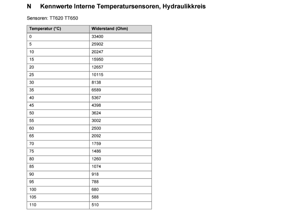
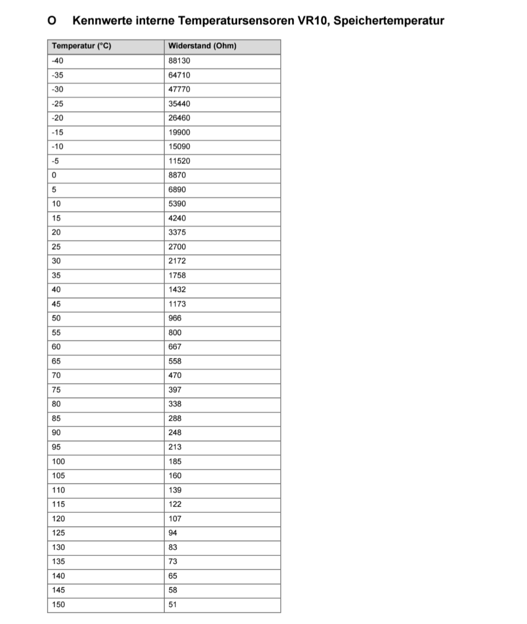
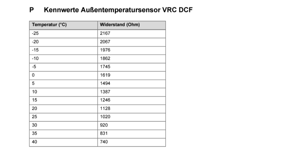
We have Vaillant manuals which contain tabulated data. I attached the full file.
For reference, here are screenshots of the tables. German only, unfortunately.
installations-und-betriebsanleitung-hydraulikstation-meh-97-6-2567180 (1).pdf (1.8 MB)
I’ve got the same problem. Any ideas where I can get sensors or if my installer needs to sort? Hp is only about 9 months old.
See above.
Turns out that the Vaillant “boiler” NTC sensors available at Screwfix for £10.55 are exactly the same as the Vaillant heat pump NTC sensors. The clip is different but they can just be pulled off and put on to the HP clips.
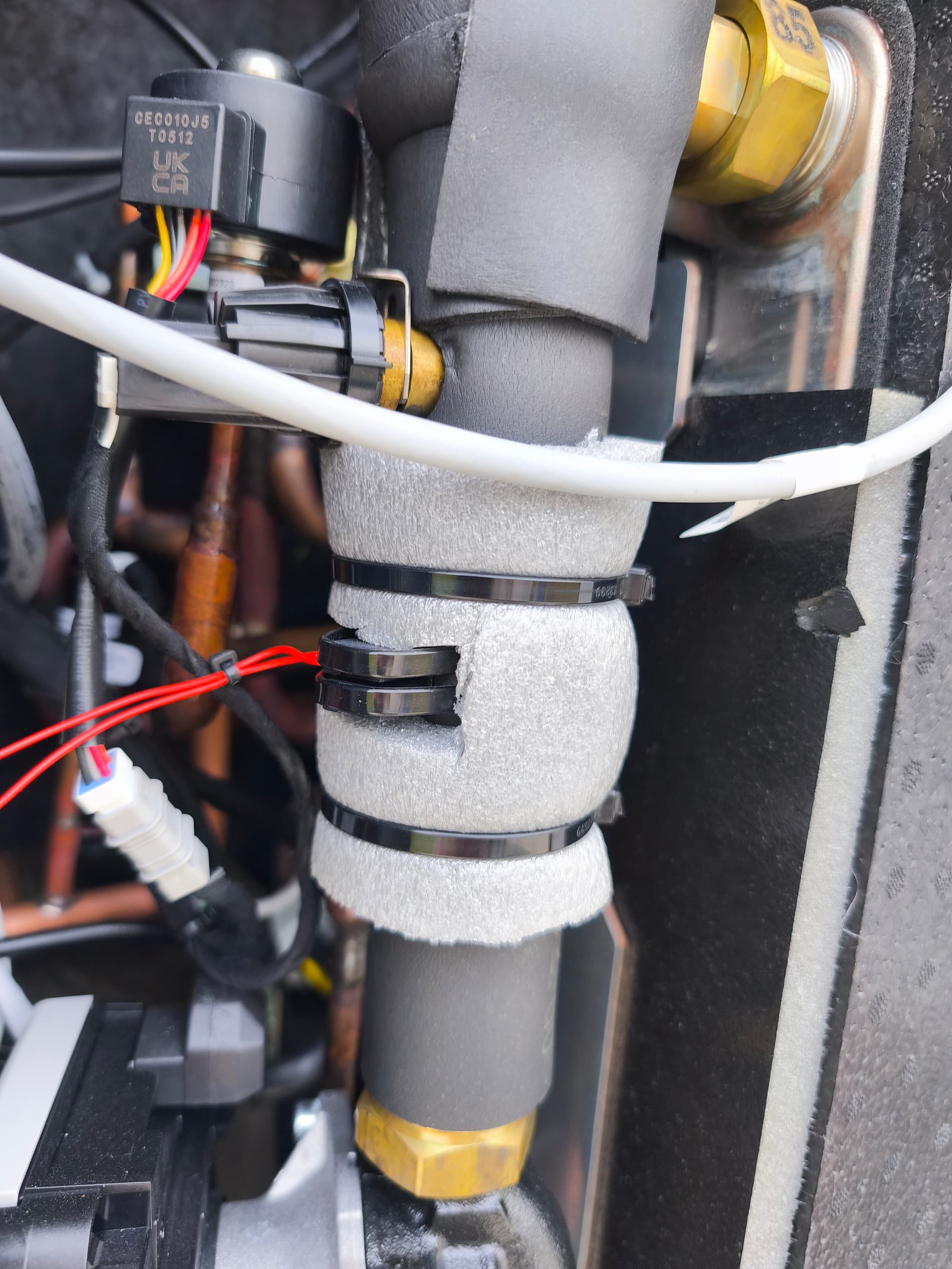
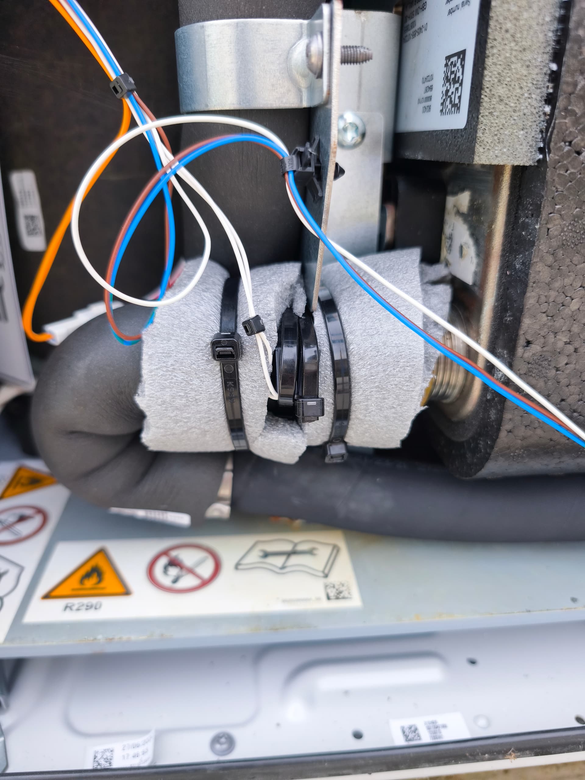
I’ve just had a look at my temperature sensors and found similar to what others have found. The insulation was wedged between the clip and the pipe on the lower sensor, not sure if it’s made a difference yet, yet to test it. I’ve also cable tied the sensors and roughly put extra lagging on (without pinching the cables) to see if that helps.
Unfortunately no difference for me. I have a 0.9k differential, return being 0.9k higher than flow, so under reporting COP I believe? Currently struggling to hit the 3’s.
I’ve tested the delta T as above, compressor off with pump still circulating but the only problem is, I do have a buffer? Will that make any difference to the test?
I’ve ordered two of the Screwfix sensors after Dan’s recommendation. Hopefully I’ll get a matching pair out of the four I’ll have to choose from.
Just to update my findings. My two Screwfix sensors arrived and I can confirm that these are exactly the same as the heat pump sensors, the clip is different but can be easily swapped around (nice one @Dan_Grey ![]() )
)
I tested my current sensors once I removed them and found a difference of 0.5k ohms which was equated to difference of 0.9 degrees. Once I got them all in one place I put them in a bowl of water to measure how close they were to each other:
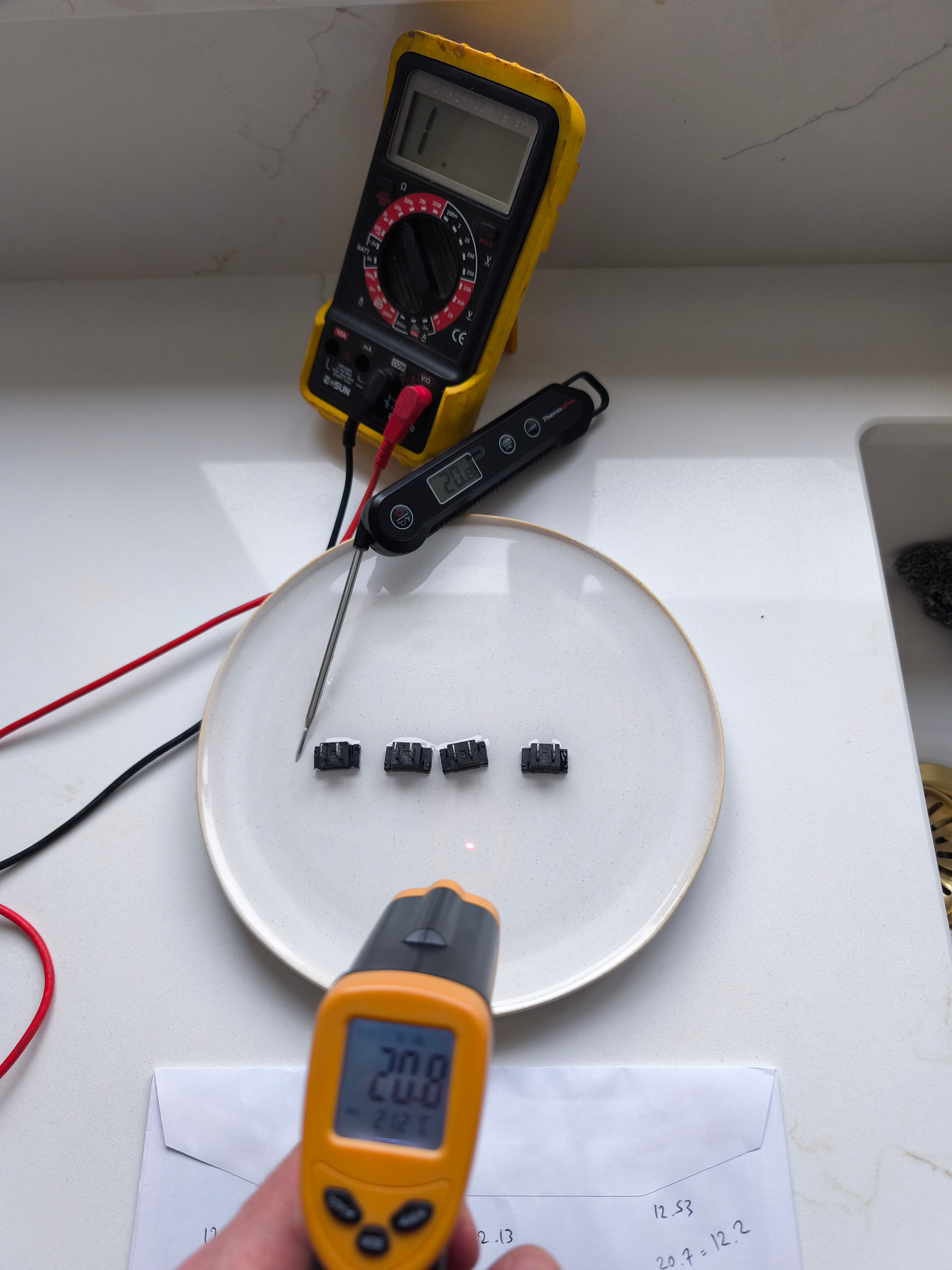
Original sensor 1: 12.12 k ohms
Original sensor 2: 12.55 k ohms
New sensor 1: 11.91 k ohms
New sensor 2: 12.17 k ohms
I ended up re-using orig sensor 1 and new sensor 2 being only 0.05k ohms difference.
I then refit the sensors, made good the insulation and taped up around the sensors. Restarted the heat pump and now have a offline Delta T of 0.1 degrees between flow and return. Happy days ![]()

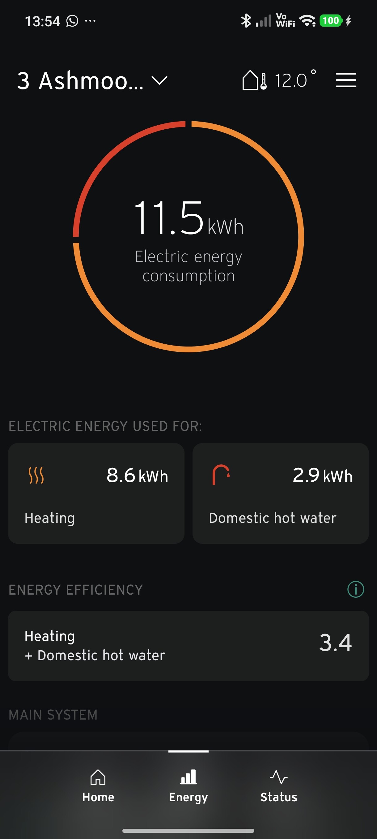
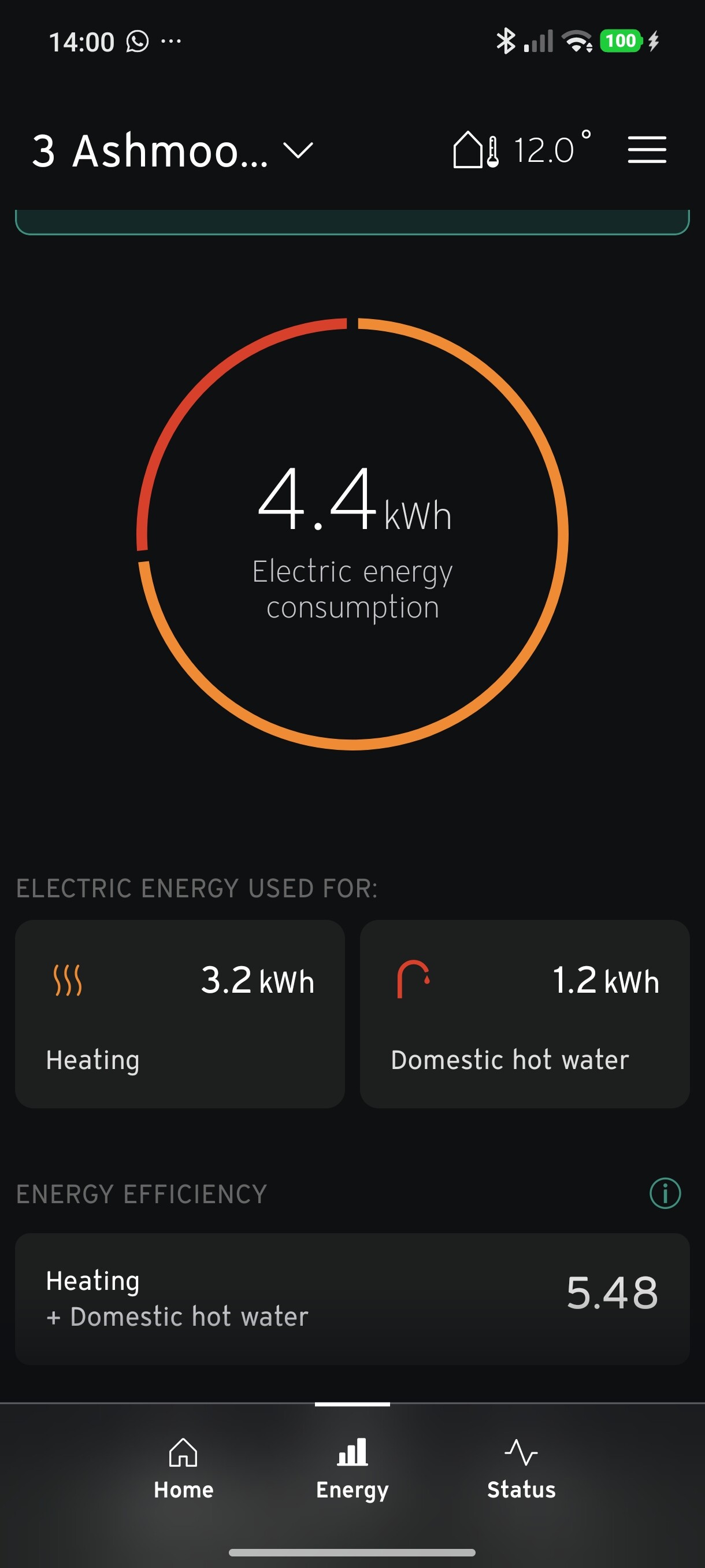
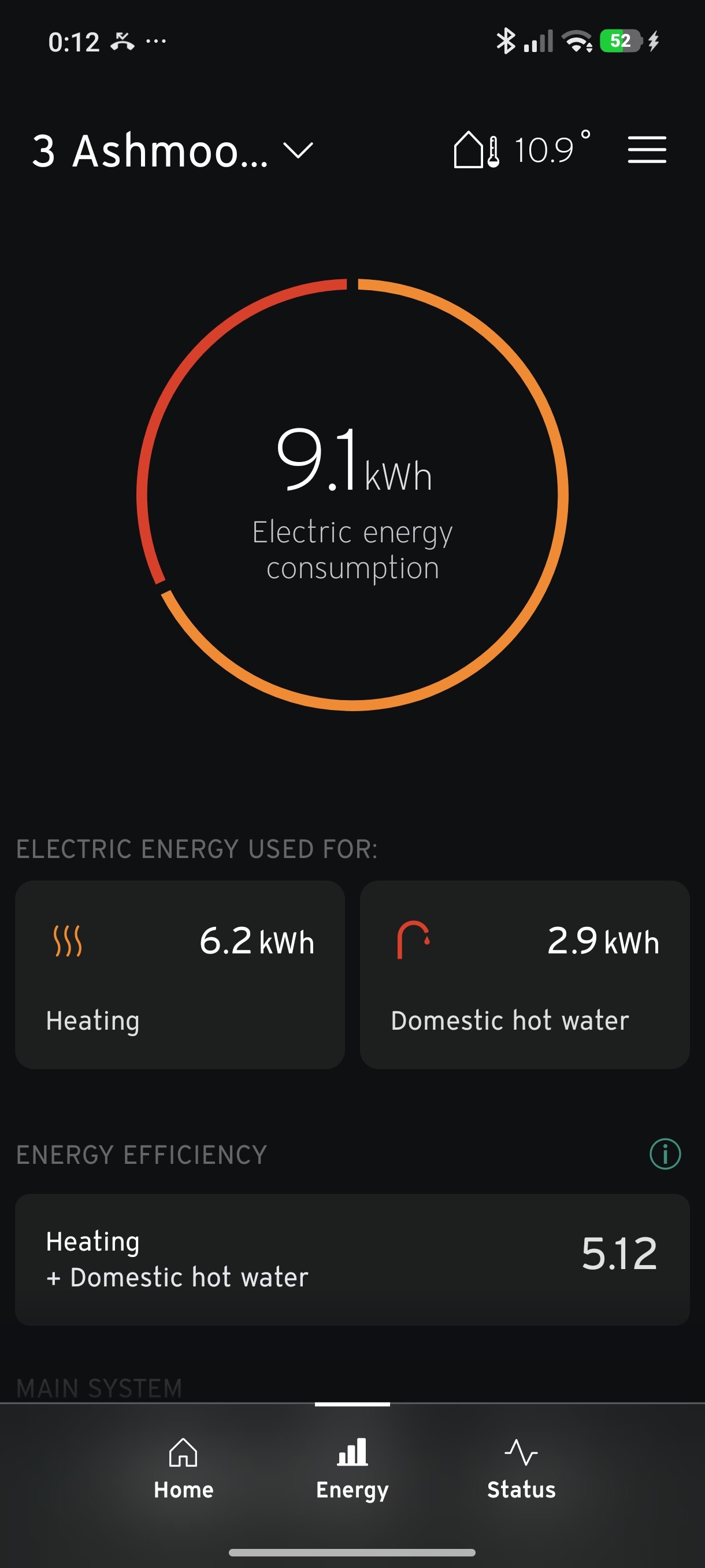
For reference, I struggled to get above 3.5 on the COP on the old sensors (return sensor was the higher reading of the two) but for the last 2 days I’ve been over 5 COP which makes more sense as my flow temps are generally really low and the house is always comfortable. The two images below are from today (so far) and 11th Feb were the outside temps were the same. Previous COP 3.4. New COP 5.48. I will continue to update COP readings to confirm, but a lot better than previous. It’s great to know that you now have two sensors calibrated closely to one another. Thanks for all the help on this.
Just a heads up, your address is partly doxxed in those last two screenshots
Nice! Very satisfying conclusion.
Just a heads-up: the adhesive on the PVC tape around the pipe insulation will go brittle and fail very quickly in the environmental conditions inside the ASHP. I’d replace it with double sided hook & loop (Velcro) on a roll; this stuff doesn’t degrade, and is easily refasten-able if needed.
Do you have glycol in the primary circuit? I don’t think Vaillant has a software switch for that and hence COP would be overestimated if Glycol were in the system, as the water+glycol mixture has a lower heat capacity.
I’m about to get a 12kw installed. So is obtaining a pair of matching NTCs the firm conclusion? This will be close enough to a MID heat meter to avoid the additional cost?
It’s the next best thing to getting a MID meter!