Most of the European 240 volt systems, as I understand them, feature a single main and everything is one-phase, one voltage. In the USA, with our 120/240 volt split-phase power system, we have two “legs” that can be at different voltages. That begs the question, is it accurate when measuring power with a single VT on one of the legs?
For those unfamiliar with the concept, the way it works is the house is fed from a center tapped transformer on a pole at the street. The center tap is grounded at the pole, and again at the service panel. Each of the two legs are nominally 120 Volts, but are 180 degrees out of phase. The potential between the two hot leads is 240 Volts.
When I connect a voltmeter to any plug, the voltages vary continuously by about +/- 1 volt (~1%) but sometimes more. Often, the variation seems to coincide with the operation of a high current 120V device like a hair dryer. In a poorly grounded service, the lights will noticeably dim or get brighter when there is a high current surge as when a motor starts.
So I put a second VT on the other leg in my house to see how this all plays out. Here are the voltage plots for the two legs on a typical morning:

We can see that the voltage wanders around between 119 and 121 (+/-1%), and for the most part, both legs are pretty much the same. To me that means the major variation is in the primary voltage feeding the transformer, or variations in loads that I’m not measuring (we share the transformer with six other houses).
There are some deviations from that theme however, and adding some other measurements helps to explain them. Voltage is on the left, power is on the right.
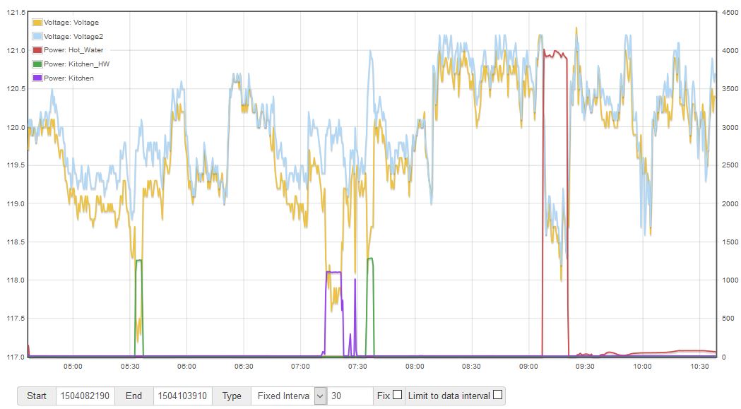
Looking at these power overlays we can see that a big dip of both legs just after 9:00am is caused by the 4000 watt/ 240v hot water heater. It pulls down both legs together, and I think that’s because of the resistance of my long entrance cable. The Water Heater is drawing 16.7 amps.
But that’s not really a problem for accuracy of the VT. Because the heater is 240V and uses both legs, a VT on either leg will still be pretty much correct.
Now take a look at a large asymmetric load (one leg only). The green Kitchen_HW is a 120V 1300W electric booster tank under the kitchen sink (its a long way from the main tank to the kitchen) and the purple Kitchen at 7:15 when we made coffee this morning with an electric coffee machine. In both cases, the high wattage 120V appliances both reduced the voltage on the hot lead of their leg, and pulled the neutral in their direction away from ground. You can see this because not only does the voltage on that leg drop, but the voltage on the other leg goes up.
So using a single VT on one leg can impact the measured power for large 120V appliances by as much as a couple of percent. It will be accurate when the VT is on the same leg, but overstated otherwise.
But all-in-all, my conclusion is that the extent and duration of the variation between the two legs is not enough to significantly impact measuring overall usage if the panel is reasonably balanced.
