Underfloor heating design

Hello. I am new to the blog and am working my way through all the posts. There is a lot to take in and a lot to learn. I am after some advice on where to look for underfloor heating design.

We have an 1800s farmhouse that has been well insulated and is running a 10 kW Vaillant aroTHERM Plus. The house is undergoing an extensive renovation, so to future-proof it I have decided to install a new insulated floor with underfloor heating. I am happy with the structure and foundations, which can take the depth needed for the insulation, and I am aware of the amount of work and potential cost involved.

I’m looking for advice on how to design the underfloor heating so that it works most efficiently with the heat pump. Can anyone recommend any resources or companies that specialise in this area? I am based in Anglesey, North Wales. I do most of the work myself but would be happy to collaborate with the right company.

Welcome, Ifan, to the OEM forum.

You’re not wrong there, and don’t forget the ‘Docs’ section, which is where you can find technical details of the OEM products as well as, in the ‘Learn’ sub-section, some theory if you need it.

Thank you. I didn’t see the the Docs section. That’s brilliant.

Hi Ifan,

It’s good to hear you’re willing to invest in improving the underfloor insulation in an old building and to use the opportunity to install underfloor heating at the same time.

I don’t believe we currently have a Docs page specific to underfloor heating. The Docs page on heat loss calculations is directly relevant, but I can think of a few UFH-specific considerations it’s probably worth capturing somewhere. Perhaps we could use this thread to collect those, with a view to turning them into a UFH-specific Docs page in due course?

Here are some notes based on my experience from installing UFH in my own new-build and from other forum posts by people retrofitting a heat pump to previously-boiler-fed UFH. They won’t all be relevant to your specific circumstances (since you already have a heat pump - and you’ll have a well-insulated floor slab) but might be helpful to others reviewing this thread later:

  1. The key to achieving the best performance from a heat pump is to transfer the heat the building needs at a low flow temperature while maintaining a high flow rate

    • The heat pump will choose its flow temperature to account for variations in heating requirements (typically based on a Weather Compensation algorithm) - with water kept flowing through all the UFH pipes all the time, but at a slightly higher or lower temperature as required
  2. The UFH mixing valves which ‘dilute’ the flow from the heat source with some of the return water from the UFH should never be used with a heat pump

    • These are generally required with a boiler, to prevent 80C water going into the UFH loops, but would significantly reduce the efficiency of a heat pump
  3. Complex multi-zone UFH controls which work by ‘switching off’ the flow to UFH zones when those are up to temperature are generally not heat pump friendly - because they reduce the flow rate once rooms start to get warm enough (and only ‘call for heat’ again when those rooms have cooled)

    • The key point here is that the heat pump should be ‘in control’ - rather than trying to make the heat pump respond to a ‘call for heat’ from another controller, like a boiler would
  4. The number of UFH zones per room and the UFH pipe spacing will need to be designed to reflect the heat loss in individual rooms (and also any differences in target temperature - e.g. slightly higher in bathrooms)

    • The objective here is to have the heating system ’naturally’ deliver the right proportion of heat to the right rooms, without per-zone controls

    • A very tight pipe spacing should allow a very low flow temperature - but if the UFH is only on the ground floor and there are radiators on upper floors those might need a higher flow temperature to work well (which means the UFH will receive that higher temperature too)

    • Rooms which can receive significant passive solar gain (or internal heat gains from other activities like cooking) probably need the ability to dial-back their heating, compared with other rooms, using valve actuator heads fitted to the manifold (under thermostatic control)

  5. The choice of floor covering can have a significant impact on the effectiveness of low-temperature UFH:

    • For maximum heat transfer, the best option is no floor covering at all. A polished concrete finish on the floor slab containing the UFH pipes can be very effective - but is not to everyone’s taste and can be expensive

    • Ceramic tiles are generally good

    • Wood flooring can be OK, but it should be ‘engineered’ wood flooring with a plywood backing, for stability

    • Carpet - especially with thick underlay - can be problematic

  6. Take the opportunity to embed some empty tubes in the concrete slab (20mm electrical conduit or similar) which can accept temperature probes, to be able to monitor the temperature of the floor slab - rather than relying on monitoring the air temperature in the room

    • These are difficult / expensive to retro-fit and can be used with thermostatic controls that limit the slab temperature, for rooms that can be prone to overheating from solar gain
  7. On a very simple installation with one UFH manifold and no radiator circuits, the heat pump’s own circulation pump will probably suffice. With multiple UFH manifolds and/or a mix of other types of emitter, secondary circulation pumps will probably be required - likely also introducing a requirement for ‘hydraulic separation’ via a Buffer Tank or Low Loss Header.

Will you just be adding UFH to the ground floor and keeping radiators on the upper floor(s)? Do you already have a Buffer Tank or similar, with secondary circulation pump(s)?

4 Likes

Thank you so much David for such a comprehensive answer. I’m still digesting a lot of what you have said.

There already loads of questions.

As far as I can tell I don’t have a buffer tank.

I am still in the design phase the area I’m preparing is a kitchen and a large living room. I will need to consider having a lower temp in the kitchen and design this into the system. One slight complications is that the ground floor is on 3 seperate levels each seperated by 2 steps. Are there any consideration i need to take? I was planning to have each level as a seperate UFH loop.

The upper floor will still have radiators.

Your response was very detailed thanks so much. Have you got any links or recommendations on books o’r resources where I can learn more about UFH?

You’re very welcome Ifan. This is a topic I’m sure will come up again, so I responded as much with a view to helping other people with the same question as addressing your specific situation.

One book I’d recommend without hesitation is Heat Pumps for the Home by John Cantor. While that covers a wide range of heat pump topics and is very much not specific to Underfloor Heating, it does have a few pages on UFH - and addresses driving UFH with a heat pump (rather than a boiler).

I’ve not read any specific ‘underfloor heating’ books myself so other people are probably better placed to advise, but publications from well-respected professional organisations should be trustworthy - for example Underfloor Heating Design & Installation Guide Book however watch out for publications which assume the UFH is being fed from a boiler, and add complex controls and mixing-down arrangements as a consequence.

Then there some videos from reliable, heat-pump-friendly heating engineers such as Heat Geek: for example: Under Floor Heating designing, spacing and balancing | Toolbox Talks

I very much expect you will end up with quite a number of loops / zones. Ideally you’d want to bring those together at a single UFH manifold, so you’ll have to consider if that might work or if you’d need multiple UFH manifolds.

1 Like

dMb . I used the CIBSE guide (ref 1) and found it valuable when discussing UFH zones, pitch sizes and flow temperatures with my contractor/plumber. It is a good guide in my opinion.

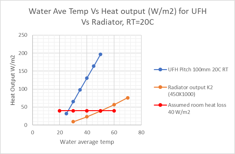
I would like to expand on point 4 above. “The number of UFH zones per room and the UFH pipe spacing will need to be designed to reflect the heat loss in individual rooms”. This is based on the room heat loss calculation to obtain the W/m2. However, you may find the contractor has a “typical pipe pitch” for a mean water temperature. You may consider future proofing the UFH with a smaller pitch to allow for a potential lower mean water temperature. Once the pipe is in the screed, then it is literally set in cement. If you intend to always have radiators in your house, then this is probably not an important point for your renovation.

This was an important point in my own house renovation. I went from a pitch of 250mm at MWT of 35C to 100mm with a MWT of 30C. John Cantor makes a similar observation from his blog. Most importantly, my house is completely UFH with no radiators (no mixing valve). The extra length of pipe loop is not that costly in the grand scheme of things. I now get the benefit of a lower flow temperature (better COP) than initially proposed.

The loop length has a maximum limitation, depending on the stockist ~100m.

Good luck with the project.

Frank

1 Like

Thanks all for your replies so far. It has taken me a while to go through everything and make sure I understand it properly. Progress is slow when trying to juggle the hundred and one other things that a house renovation requires.

I bought the John Cantor book, which has clarified a lot of the technical aspects of heat pumps for me, so thank you for that recommendation.

I have now reviewed the system that has already been installed in light of this information. It includes a Honeywell Home Evohome setup, with each radiator controlled by its own smart thermostat. From what I understand, this type of zoning may not be ideal for heat pump efficiency. I am also uncertain how this system will integrate with the underfloor heating.

The house is two storeys, with radiators remaining upstairs. From what I gather, I will likely need to run the system with a buffer tank to achieve proper hydraulic balance. What effect is the buffer tank likely to have on the overall system efficiency? Is there any way to avoid using a buffer tank and instead have the heat pump control the entire system directly?

Based on what has been discussed so far, I have realised that the gaps in my understanding are greater than expected, and I think it would be sensible to bring in an expert to assist with the system design.

I would be interested to hear any recommendations or advice on getting the UFH system designed. Can anyone suggest designers or companies that specialise in integrating UFH with heat pumps, particularly those focused on maximising system efficiency? So far, my searches have mostly returned ECO4-type installers rather than design specialists.

1 Like

It sounds like you’re taking a considered and pragmatic approach, which I’m sure will pay dividends in the long run. Your new ground floor will be a big investment, with scope for ‘repent at leisure’ if it doesn’t perform the way you’d like it to, so bringing in some design expertise at this stage is probably prudent. I can completely relate to the challenge of having countless other things to worry about in any major building project!

It is certainly the case that if the whole heating system can be run using only the primary circulation pump (i.e. the pump that’s moving water through the heat pump’s heat exchangers) the overall performance will tend to be better, because:

  • There’s always a saving on the running costs of additional circulation pump(s)

    • My data shows a Grundfos Alpha2 secondary circulation pump consumes an extra 20W all the time it’s running, so 0.48 kWh per day if running 24x7 (about 12.5p per day)
    • While this 20W isn’t ‘wasted’, it’s heating the property at 100% efficiency, not 400% efficiency
  • The flow temperature from the heat pump will generally be preserved all the way to the emitters, without being ‘diluted’ by some of the return as can sometimes happen with a buffer tank / low-loss header

With purely radiator-based systems, which have a relatively low pressure loss, it’s generally not too difficult to run with just the primary circulation pump.

However, with underfloor systems, the water is having to go through hundreds of metres of additional pipework, which means the pressure loss will be significantly higher. Using a tighter UFH pipe spacing, to maintain high heat output at low flow temperatures, means even more pipe and even more resistance to the flow.

If you try to combine radiators with UFH, connecting those two sub-systems ‘in parallel’ with each other - using a single pump - the vast majority of the flow is going to take the easy route, through the radiators, with minimal flow through the UFH. That’s generally the opposite of what you want if the UFH is on the ground floor and the radiators are upstairs (given that heat rises, and people often prefer upstairs to be cooler than downstairs). I suppose you could try to restrict the flow through the radiator circuit to try to ‘balance’ the flow with the UFH, but then the heat output from the radiators will suffer.

So if you have UFH you’re likely to need at least one secondary circulation pump. The question then is how the multiple circulation pumps interact with each other. In some cases people have had issues with secondary pumps ‘over-running’ the primary pump, recirculating some return water and thoroughly confusing the heat pump’s control algorithm by making it think its flow was cooler than it actually was - see e.g. this (long but interesting) forum thread: My Journey to an efficient ASHP for a system with radiators and UFH (each with their own secondary circulation pump) which was retro-fitted with a heat pump and some sort of buffer arrangement that didn’t separate the flows properly.

Properly designed and installed buffer tanks or low-loss headers help by providing “hydraulic separation” between multiple pumped circuits. Each pump is able to operate independently, especially where there are thermostatic controls which switch some of the pumps on and off at different times. My own experience with a low-loss header is that they are very effective at isolating the pipework circuits; with multiple ‘downstream’ pumps running (pushing water through the radiators and UFH) there’s only a tiny flow through the ‘upstream’ circuit (the heat pump) until the primary circulation pump starts up.

While the inclusion of buffer tanks can be a symptom of lazy design or lack of understanding on the part of an installer, in the right circumstances they are beneficial - or at least not detrimental. See for example this blog post where Michael de Podesta did a controlled experiment of removing a low-loss header from his installation, with no discernible change to the efficiency: Heat Pump Experiment | Protons for Breakfast

While plenty of posts on these forums seem to regard buffer tanks as always A Bad Thing, that’s unfair. When there’s a good reason to include them - and provided they’re not being treated as some sort of ‘reservoir’ of heat that the heat pump ‘charges up’, having the secondary pumps draw from that reservoir as required (or not), they’re fine. In general, you want the secondary pumps running all the time, so that any heat the heat pump sends into the buffer is immediately circulated around the house.

Or, much more concisely, my advice is not to be concerned about including a buffer / low-loss header if your installation is complex enough to benefit from one.
2 Likes

Great answer. Thanks again.

I am at the stage now where I need a disgner. Has anyone got any recommendations? Or any way that I can find someone who is an expert that’s not an ECO4 installer.

1 Like